Clotheshanger

For this project I went through Daniel Schiffman’s tutorial and found the section on toxiclibs really interesting. I stuck to the springs and soft body square section and decided to do a clotheshanger. The toxiclibs springs have a very interesting texture to them compared to the meshes in processing or PBox2D, and fiddling around with constants in meshes are very fun.

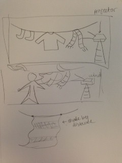
Anywho, the point of my projection was to have the arrow keys control the wind direction so, as people walk by, they can experience the illusion of blowing cloth. I wanted to make clothes-shaped meshes, but I had enough trouble with the soft body squares, so that didn’t happen… I also found a beautiful example of coloring meshes by shading places darker according to distance between springs, but I didn’t know how to fill in the spaces between springs individually, so that didn’t happen either… Also, this projection was on a smaller scale, so Rachel and I just pretended to blow puffs of wind or blow a hairdryer at the cloth. I did struggle with the physics quite a bit, and there are still glitches within my toxiclibs code, but overall this assignment was much more fun. This might be because of the hands-on aspect of the project or because I had fun partnering up with Rachel. I also really like working with the pico projector and arm. I want them so badly now.

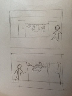
Here are some extremely rough sketches:

photo (4)

photo (6)

Froggies!

For my ecosystem, I started out with a fish pond because I remember a while back google had a random koi fish app somewhere on the internet. I tried searching it up again but I only see different android apps. I tried modelling the tail movements of the fish, but those ended up looking like tapeworms… So, I reused the curveVertex design that I featured in my first lasercut and added eyeballs. The lillypads have a gravitational force, so it looks like they try to hide from you. I applied Daniel Schiffman’s flocking examples to separate the fishes so they all wouldn’t go into the same spot due to the averaging of gravitational pulls. When you click the lillypads to make them disappear, the gravitational force gets added to the other lillypads so the fish don’t slow down. Pressing the space bar adds more lillypads. The lillypads, by the way, are cardioids, and they oscillate up and down and cause ripples. That was the funnest part of this project.

Then I decided to add frogs. I wanted them to leap onto a different lillypad when you clicked on one so that you would be “scaring them away”, but I had enough problems just getting them to jump on different lillypads. Giving them velocities ended up in hours of project failures, so this became my end product. Anywho, the best part about them is that they blink.

Here is my openprocessing upload, but the Javascript version of the code is far glitchier than the regular version run on processing:

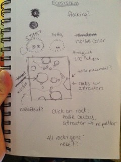
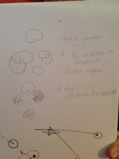
Here are my sketches (notice I started out with the idea of Puffles hiding under rocks instead of a fish pond):

photo (5)
frog

photo 1

Jun-Looking Outwards 3

void ()

It took me a little while to realize that the projection is under water, and the black particles that travel up are bubbles. Apparently, the bubbles are created according to frequency of sound, and the movement of the bubbles are then caught by a sensor and are used to create a real-time visual projection onto the bubble wall. All elements come together to create an audiovisual experience. I find the movements of the bubbles and projection quite calming, and projection in water is kind of unique. I’m not sure why the project is named “void ()”, unless it’s the default video title if no titles are entered? But it sounds cool.

atOms – Ryo Kishi

This project is fairly different from the art projects I usually focus on. He uses air flow to suspend balls in air, and then used the rotations of the air blowers controlled by Arduino to choreograph some kind of “dance”. I find the idea and the physics quite ingenious. It seems like he is still working on this. It’d be cool to see some fancier choreography, such as incorporating varying air flow force if it’s possible, so the balls would suspend at different heights.

Pixelate

https://www.creativeapplications.net/openframeworks/pixelate-guitar-hero-style-eating-game-which-detects-food-you-are-eating/
A very creative outtake on an old concept. This project turns eating into competitive gaming. The fork uses the difference in various fruits’ current resistance to figure out which food the player is picking up. Arduino is built into the table that shows the players what food they’re supposed to eat. The presentation of the game looks like 8-bit old-school, an homage to the old pixelated games. I’m not sure how they’re generating the food order, but I could see a potential problem with running out of a certain food on the plate. Also, although a purpose of this project is to encourage healthy eating, making eating competitive could make competitive players rush while eating (maybe not chew thoroughly before swallowing), which isn’t healthy. Anyway, I bet they had a really good time during the development of this project. Yum.

Perception – Volvoxlabs

https://www.creativeapplications.net/environment/perception-of-consequence-by-volvoxlabs/
[It seems like the main focus of this project, the animation, has little to do with Arduino. The Arduino use is in the real room viewing of the video, though I’m not exactly sure what… fans, maybe? But man, the animation looked cool.] Watching this video made me feel uncomfortable in my stomach and feel captivated at the same time. The general gist looks like it’s two blobs of milk in vague shapes of beasts fighting against each other (it’s supposed to simulate human states and emotions). The animation is projected on a fabric on a custom shaped structure to make it seem more “organic”.

White is a color.

That’s right folks – we’ve been lied to this entire time by our art professors and the like that white is not a color, but a tone (or maybe it was just me). I had recently received an email from Golan informing me that, despite how it appeared to be suitable for cutting, my laser cut design failed. Because white is a color.

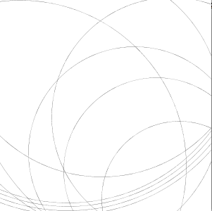
I am assuming what happened with my design was that, because I constructed the arcs with the ‘arc’ primitive and used strokeWeights / color manipulation to create the illusion of an outlined curve, the laser cutter misinterpreted the white strokes – which were meant to be holes – as filled-in shapes.

My code will have to undergo some revisions; and the code for creating the arcs will not be as short and sweet as I hoped it would be. Thankfully, Golan gave me some reference code (below) to assist me with making the necessary changes. Regardless of the additional work that must be done to make the design compatible with the laser cutter, this is certainly a valuable learning experience that will be useful for my future laser cutting endeavors.

I find this incident to be funny, because while we can make judgments on how a program or machine behaves based on what we see visually, things can be interpreted in a completely different way. My high school computer science teacher once told us that our programs are only as smart as we are, but I think there are some cases where they can be just a little bit dumber.

I hope none of you guys ran into the same issue that I had. 😛

/*
Ticha 
White is a color. Your lasercut failed. 
Run this program to understand the solution.
Please write a blog post explaining why this is so.
*/

void setup() {
  size(450, 400);
}

void draw() {
  background (220, 255, 220); 
  noFill(); 
  
  // Properties of the arc
  float arcCenterX = 300;
  float arcCenterY = 200;
  float angleA = radians (mouseX); 
  float angleB = radians (mouseY); 
  float startAngle = min(angleA, angleB); 
  float endAngle   = max(angleA, angleB); 
  float innerDiam  = 160;
  float outerDiam  = 200;
  
  float averageDiam = (innerDiam + outerDiam)/2;
  float averageRadius = averageDiam/2;
  float littleArcDiam = (outerDiam - innerDiam)/2; 

  // draw the center points of the endcap arcs
  float p1x = arcCenterX + averageRadius * cos (startAngle); 
  float p1y = arcCenterY + averageRadius * sin (startAngle); 
  float p2x = arcCenterX + averageRadius * cos (endAngle); 
  float p2y = arcCenterY + averageRadius * sin (endAngle); 
  stroke (255, 120, 0, 120); 
  ellipse (p1x, p1y, 3, 3); 
  ellipse (p2x, p2y, 3, 3); 

  // draw the spine, which is just for reference
  stroke (255, 120, 0, 120); 
  arc(arcCenterX, arcCenterY, averageDiam, averageDiam, startAngle, endAngle);

  // draw the main arcs (inner and outer), in lblue
  stroke (0, 0, 255); 
  arc(arcCenterX, arcCenterY, innerDiam, innerDiam, startAngle, endAngle);
  arc(arcCenterX, arcCenterY, outerDiam, outerDiam, startAngle, endAngle);

  // draw the endcap arcs, in purple
  stroke (255, 0, 255); 
  arc(p1x, p1y, littleArcDiam, littleArcDiam, startAngle-PI, startAngle ); 
  arc(p2x, p2y, littleArcDiam, littleArcDiam, endAngle, endAngle+PI );
}
Chloe – LaserCut Screen (In Progress)

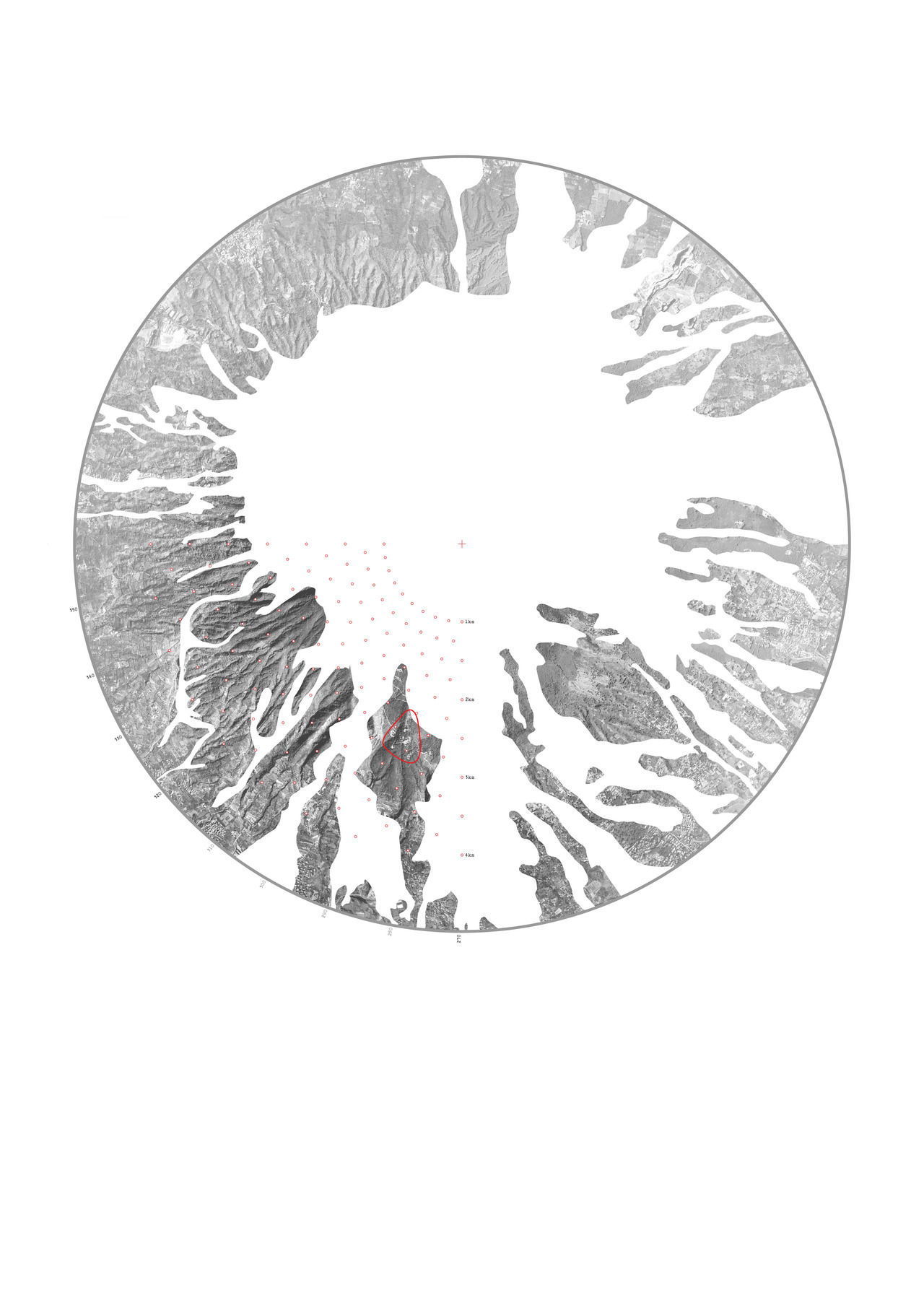
Inspired by this topography-style graphic I found while scrolling through Tumblr, as well as Ian Dixon’s ‘Roots’, I studied his code, along with other organic and Perlin noise simulations to try to recreate the organic, flowy blobs, and enclosing them within a circle to make for an interesting silhouette I wouldn’t have the patience of cutting by hand.

Unfortunately I haven’t been able to figure out how to get the outlines, as opposed to trying to be smart and having white eclipse trails over a black circle. At the same time I have yet to figure out how to implement a repulsion system for each drawing particle so as to make them stay a little more separate. Hopefully I can figure out something soon.

./wp-content/uploads/sites/2/2013/10/organicircle4.pdf

organicircle4

Light on Water (Lasercut Screen Attempt)

Concept

My concept for the lasercut screen was to have a screen with a pattern of cutouts similar to the pattern of highlights on water/waves.

reference photos of light on water


A trace of a wave image in illustrator. A trace of a wave image in illustrator.

The Tale of Many Dead Ends

I did not manage to create the kind of pattern that I wanted to. I tried a bunch of things that didn’t work, then ended up using one of my more interesting mistakes for the screen. These are some of the things that didn’t work:

Creating Ripple Force Field

ripples I couldn’t manage to turn ripples into a flow field.

One failed approach was to create a flow field (like the one described in Chapter 6 of the Nature of Code) using ripples to determine the strong and weak points of the field. I think this failed because I didn’t spend enough time thinking about how to take circles—graphic ripples—and translate them into a flow field.

Note: I also couldn’t find the chapter in the Nature of Code Book while I was working on it—refound it while writing this. It would have been helpful to review while trying to code the ripples thing.

Playing with Physics

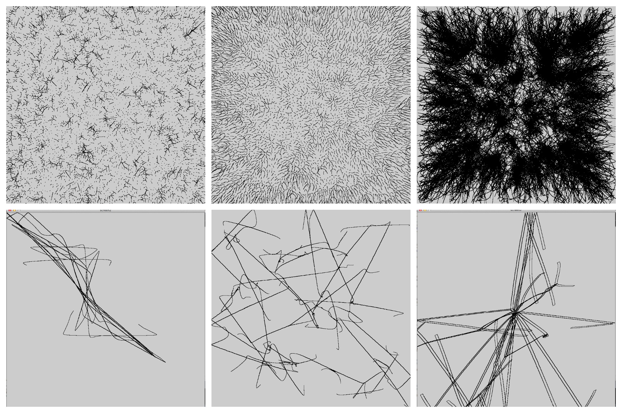
After I figured out that the early universe had similar patterns to light on water, I decided to try to simulate distributed particles with certain masses and gravity forces. I spent a fair amount of time just messing around with repulsion forces, masses, and velocities, trying to see if I could get the particles to attract/repulse into the right pattern (with the particles drawing trails behind them).

Things that happened while I played with the constants in my particle simulations. Things that happened while I played with the constants in my particle simulations.

Clicking to Disturb Particles

My next attempt was to just set up a field of particles, then apply a repulsive force when and where the mouse was clicked. I figured I could create my own waves until a pattern I liked emerged, then trace through or around the particles to create my pattern. The first part of this approach worked, but I could not find a good enough approach to tracing.

Connect Closest

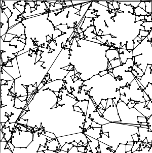
The first thing I tried was just having particles connect to the ones closest to them. This approach was not well thought out, and that became apparent very quickly when I implemented it. Connecting the particles created overlapping geometric shapes that weren’t really in the pattern I wanted, and which would also probably leave me with a shredded piece of board rather than a cut out screen if I used it with the laser cutter. (Since the approaches flaws were apparent, I didn’t fix the bugs in it, which explains some of the random seeming lines in the screenshot below.)

Closest Connect

Blob Tracing

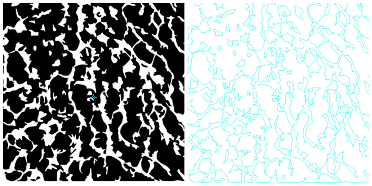
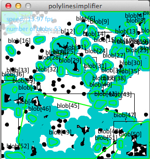
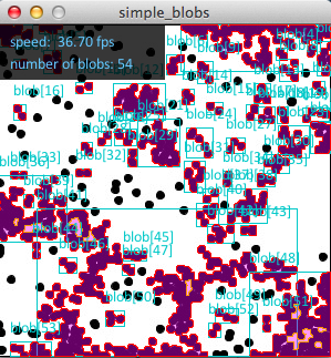
I decided to try tracing the darkest areas of the particles in order to create the forms I wanted. I looked at many different blob tracing libraries, some of which worked and some of which didn’t:

  • BlobDetection – didn’t work
  • openCV blobs – didn’t work (meant for video)
  • dieWaldCV – kind of worked, but didn’t smooth the edges of my blobs enough to my taste. This might have ended up working if I had played with the color/gradients of the blobs themselves.

Screen Shot 2013-10-10 at 12.13.39 AM Screen Shot 2013-10-10 at 12.17.16 AM


One approach I didn’t try was making the blob tracing libraries trace the white areas rather than the black dots. That might have gotten me closer to what I wanted, but it also might have just produced ugly blobs.

Code

Code: https://github.com/juliat/lasercut-screen

Side Note: Hopefully Helpful Helper Function

I wrote a really basic helper function that takes in a normal stroke and draws an outlined version of it. This may be useful to others: helper function code

Ralph-Assignement-06-LasercutScreen (UPDATED)

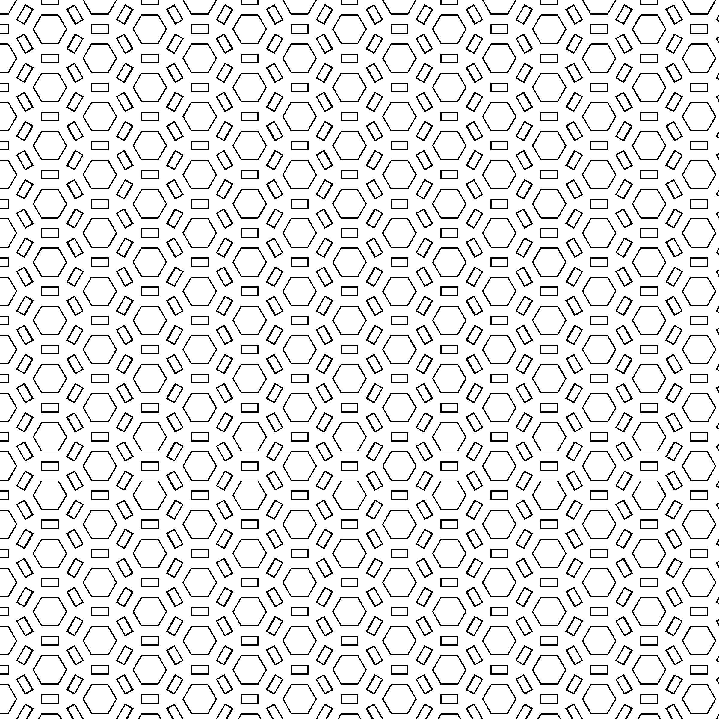
The pattern currently does not utilize a particle system. I am still working on making each hexagonal unit (as a particle) stack on top of each other in an organic way using repulsion force. While I’m still tweaking that, I put together this image as my placeholder piece for now.

poop
poop

UPDATE!
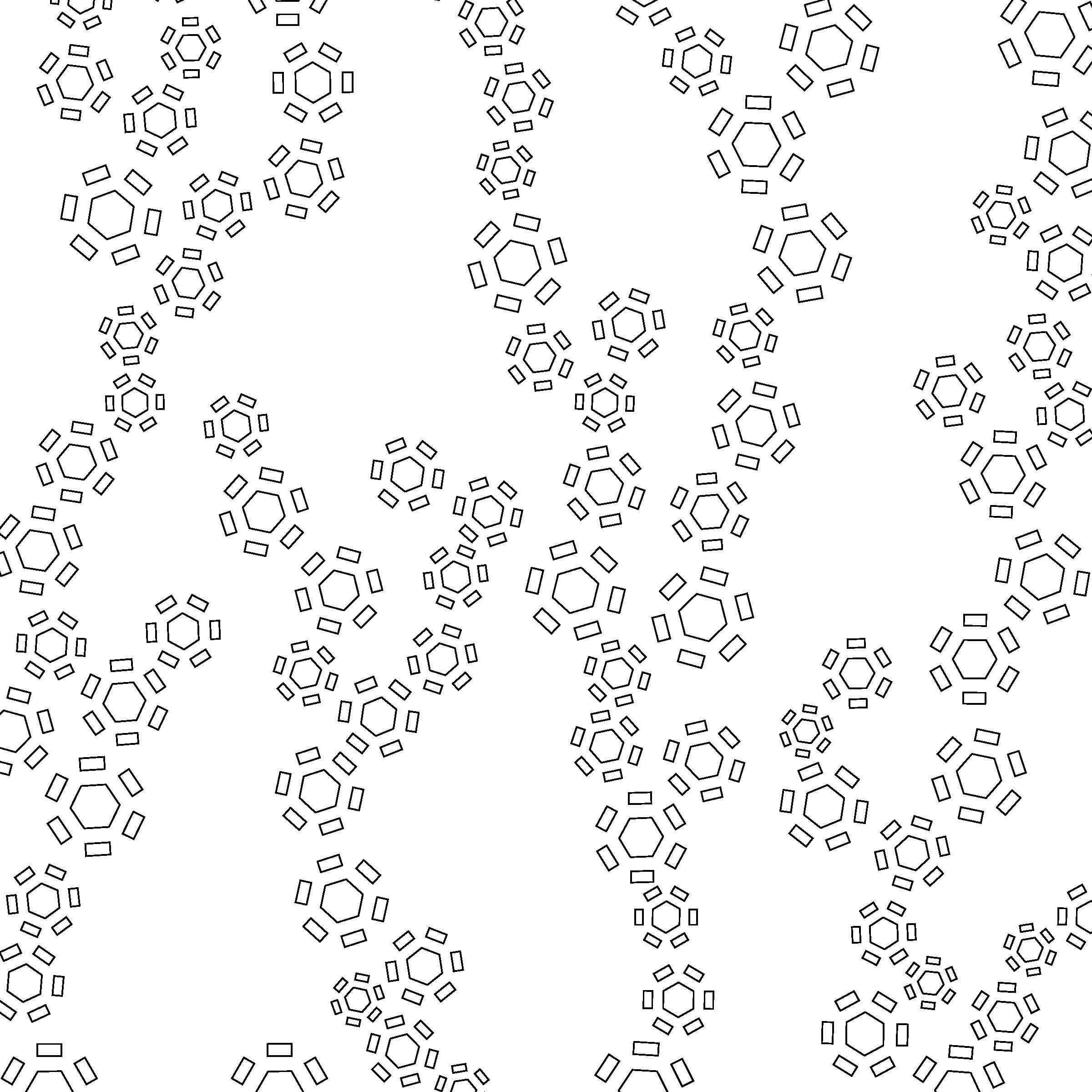
The code is working precisely as I described now. Here’s the son-of-a-bitch:
Link to the piece on OP: https://openprocessing.orgsketch/113878

poop poop

ArrayList myPattern;
int maxPattern = 1;

void setup() {
  size (864, 864);
  myPattern = new ArrayList();
}

void draw() {

  background(255);

  for (int i=0; i= ithPattern.py) {

        float jx = jthPattern.px;
        float jy = jthPattern.py;
        float ix = ithPattern.px;
        float iy = ithPattern.py;
        float distance = sqrt((jy-iy)*(jy-iy) + (jx-ix)*(jx-ix));

        //radius of pattern
        if (distance < (jthPattern.l*2.6 + ithPattern.l*2.6)) { 
          myPattern.get(i).addForce(0, 0);
          ithPattern.vy = 0;
        }
      }
    }

    ithPattern.update();
    ithPattern.render();
  }

  if (maxPattern < 400) {
    maxPattern ++;
  }
}

//=========================================================================


class Pattern {
  float l;
  float ptheta;
  float px;
  float py;
  float vx;
  float vy;

  //constructor for Pattern
  Pattern(float x, float y, float theta, float rl) {
    ptheta = theta;
    px = x;
    py = y;
    l = rl;
  }

  // Add a force in. One step of Euler integration.
  void addForce (float fx, float fy) {
    float ax = fx;
    float ay = fy;
    vx += ax;
    vy += ay;
  }

  void update() {
    px += vx;
    py += vy;
    if (py > height) { //land
      py = height;
    }
  }

  void render() {
    pushMatrix();
    translate(px, py);
    rotate(ptheta);
    noFill();
    strokeWeight(1);
    line(-l, 0, -l/2, round(-0.866*l));
    line(-l/2, round(-0.866*l), l/2, round(-0.866*l));
    line(l/2, round(-0.866*l), l, 0);
    line(l, 0, l/2, round(l*0.866));
    line(l/2, round(l*0.866), -l/2, round(l*0.866));
    line(-l/2, round(l*0.866), -l, 0);
    for (int i = 0; i < 6; i++) {
      rotate(PI/3);
      rect(-l/2, 3*l/2, l, l/2);
    }
    popMatrix();
  }
}

Kristina — Screen cut

[EDIT]

Since my last lasercut screen design proved to be an abysmal failure… here is the follow up.

./wp-content/uploads/sites/2/2013/10/frame-0031.pdf
./wp-content/uploads/sites/2/2013/10/frame-0060.pdf
./wp-content/uploads/sites/2/2013/10/frame-0300.pdf
./wp-content/uploads/sites/2/2013/10/frame-0383.pdf
./wp-content/uploads/sites/2/2013/10/frame-0415.pdf
./wp-content/uploads/sites/2/2013/10/frame-0784.pdf
./wp-content/uploads/sites/2/2013/10/frame-0791.pdf
./wp-content/uploads/sites/2/2013/10/frame-2213.pdf
./wp-content/uploads/sites/2/2013/10/frame-2654.pdf

Although it turns out there is in fact a way to flatten images like the first one I produced in Rhino 3D… I would be beyond pleased if that worked, but until then… I will lasercut one from the above selection as soon as I can figure out how to find/book/use the lasercutter.

This design is extremely simple, made by a series of small circles attracted to a central circle. In this way, I hope to see the most light come through at the center of the design.


./wp-content/uploads/sites/2/2013/10/Kristina-LaserScreen-copy.pdf

Here is my final version of my PDF — save for having to tweak some things to get it to laser cut. The idea behind having just the barest most minimalistic way is that snow itself is minimalistic/white. Additionally, I wanted something which wouldn’t completely delete Os and Ds on the laser cutter.

Adam-Assignment-06-LasercutScreen

Warp

I was thinking about Wood Bora for this project and imagining what would happen if they co-ordinated their “boring” efforts.

I wanted to create a point mesh that would then be distorted by a point travelling over it using an inverse square relationship.

Early attempts:
Screen Shot 2013-10-03 at 11.47.21 AM

Screen Shot 2013-10-03 at 11.47.43 AM

Unfortunately I was unable to get the points to stay in their new positions and had to borrow some code of the internet.

Using an adaptation of code that Golan had written for me and some help from Miles. The code is no longer borrowed, but my own!

Final attempts:

./wp-content/uploads/sites/2/2013/10/5.pdf
./wp-content/uploads/sites/2/2013/10/4.pdf
./wp-content/uploads/sites/2/2013/10/3.pdf
./wp-content/uploads/sites/2/2013/10/2.pdf
./wp-content/uploads/sites/2/2013/10/6.pdf
./wp-content/uploads/sites/2/2013/10/1.pdf

int numParticles = 19600;
PVector[] positions = new PVector[numParticles];

void setup() {
  size (700, 700); 
  smooth();
  noStroke();
  noFill(); 
  fill(0);

  for (int y=0; y<140; y++) {
    for (int x=0; x<140; x++) {
      positions[y*140+x] = new PVector(x*5, y*5);
    }
  }
}

void draw() {
  background(255); 
  float xOffset = 0; 
  float yOffset = 0;
  float xScale = 5; 
  float yScale = 5; 
  float distortion = .08; 

  for (int y=0; y<140; y++) {
    for (int x=0; x<140; x++) {
      int index = y * 140 + x;
      float px = positions[index].x; 
      float py = positions[index].y;

      if (mousePressed) {

        float dx = px - mouseX;
        float dy = py - mouseY;
      
      float dh = sqrt(dx*dx + dy*dy); 
      if ( dh > 0) {
        px += distortion * dx/pow(dh, .7);
        py += distortion * dy/pow(dh, .7);
      }}
      //rect(px, py, 1, 1);
      positions[y * 140 + x] = new PVector(px, py);
      rect(positions[index].x, positions[index].y, 1, 1);
    }
  }
}

Snowflake-like

./wp-content/uploads/sites/2/2013/10/laser_cut1.pdf

Was supposed to go for shattered-glass look, but shattered glass has a lot more randomness… So it turned out looking like a spider web. Heh. Had quite a bit of trouble not getting the lines to overlap, which made adding randomness a lot harder.

Updated to draw shapes using only black lines (no whites), and made the border of the shapes proportional to closeness to center. Had to review some trig to do this. Now it looks like a snowflake people can cut out just from paper. Eh..

import processing.pdf.*;

ArrayList< Arraylist > allVeins;

float defaultDP; //default percentage of length of vein
float currDP;
int defaultV; //base # of veins
int currV;
boolean recording;

void setup() {
  size(864, 864);
  background(255);
  recording = false;

  allVeins = new ArrayList< Arraylist >();

  defaultDP = 1.0;
  defaultV = 24;
  currDP = defaultDP;
  currV = defaultV;

  setNewVeins(currV);
}

void setNewVeins(int n) {
  allVeins.clear();
  setLvl(n, 1.0);
}

void setLvl(int n, float percent) {
  ArrayList veins = new ArrayList< Vein>();

  for (int i=0; i lvl = allVeins.get(0);
  int n = lvl.size();

  beginShape();
  for (int i=0; i lvl0 = allVeins.get(j);
  int n = lvl0.size();
  float da = 0.07;
  float dd = 0.2;

  ArrayList lvl1 = allVeins.get(j+1);

  for (int i=0; i