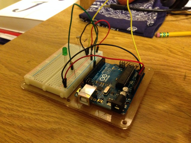
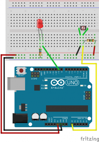
Photoresistor

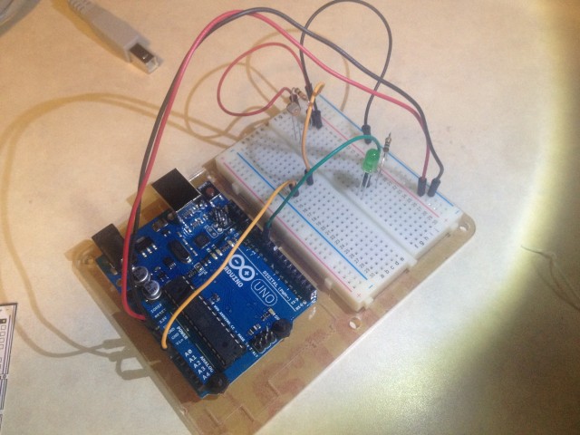
CAM01844Screen Shot 2014-10-22 at 16.49.48


/*
 * A simple programme that will change the intensity of
 * an LED based  * on the amount of light incident on 
 * the photo resistor.
 * 
 */

//PhotoResistor Pin
int lightPin = 0; //the analog pin the photoresistor is 
                  //connected to
                  //the photoresistor is not calibrated to any units so
                  //this is simply a raw sensor value (relative light)
//LED Pin
int ledPin = 9;   //the pin the LED is connected to
                  //we are controlling brightness so 
                  //we use one of the PWM (pulse width
                  // modulation pins)
void setup()
{
  pinMode(ledPin, OUTPUT); //sets the led pin to output
}
 /*
 * loop() - this function will start after setup 
 * finishes and then repeat
 */
void loop()
{
 int lightLevel = analogRead(lightPin); //Read the
                                        // lightlevel
 lightLevel = map(lightLevel, 0, 900, 0, 255); 
         //adjust the value 0 to 900 to
         //span 0 to 255


 lightLevel = constrain(lightLevel, 0, 255);//make sure the 
                                           //value is between 
                                           //0 and 255
 analogWrite(ledPin, lightLevel);  //write the value
}

Circuit #9 – The Photoresistor

The code as seen in the ARDX Kit book:

/*
  * A simple programme that will change the intensity of
  * an LED based  * on the amount of light incident on 
  * the photo resistor.
  * 
  */

//PhotoResistor Pin
int lightPin = 0; //the analog pin the photoresistor is 
                  //connected to
                  //the photoresistor is not calibrated to any units so
                  //this is simply a raw sensor value (relative light)

//LED Pin
int ledPin = 9;   //the pin the LED is connected to
                  //we are controlling brightness so 
                  //we use one of the PWM (pulse width
                  // modulation pins)
void setup()
{
  pinMode(ledPin, OUTPUT); //sets the led pin to output
}

/*
 * loop() - this function will start after setup 
 * finishes and then repeat
 */
void loop()
{
  int lightLevel = analogRead(lightPin); //Read the
                                         // lightlevel
  lightLevel = map(lightLevel, 0, 900, 0, 255); 
        //adjust the value 0 to 900 to
        //span 0 to 255

  lightLevel = constrain(lightLevel, 0, 255);//make sure the 
                                             //value is between 
                                             //0 and 255
  analogWrite(ledPin, lightLevel);  //write the value
}

Here is the video of the working circuit:

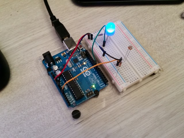
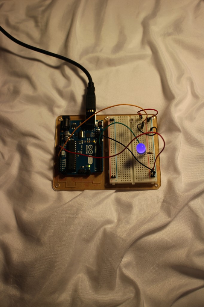
Here is a picture:

circuit9

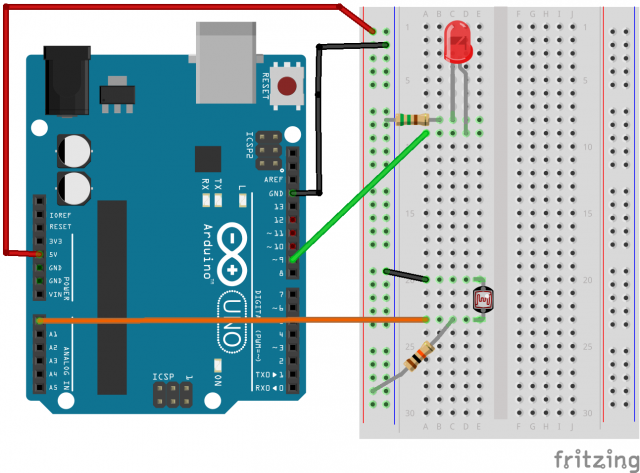
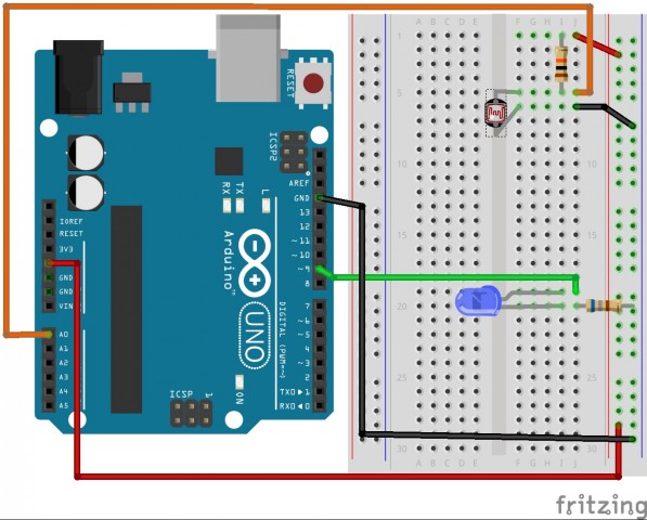
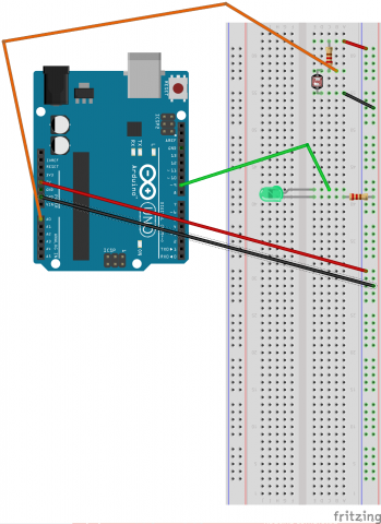
Here is a fritzing diagram:

photoresistor_diagram_mkellogg


Written by Comments Off on Circuit #9 – The Photoresistor Posted in Uncategorized

Arduino project #1

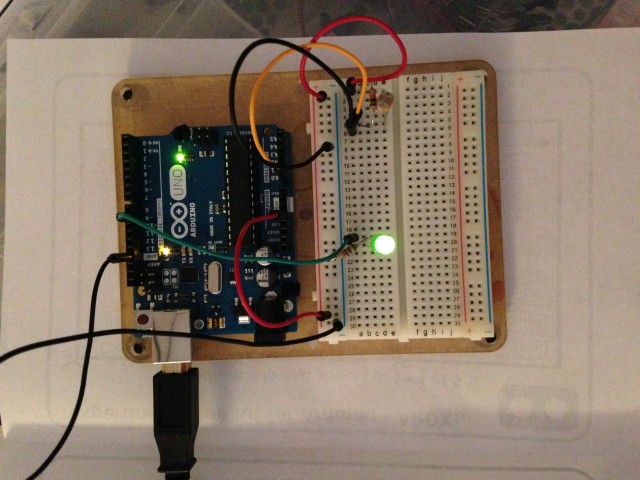
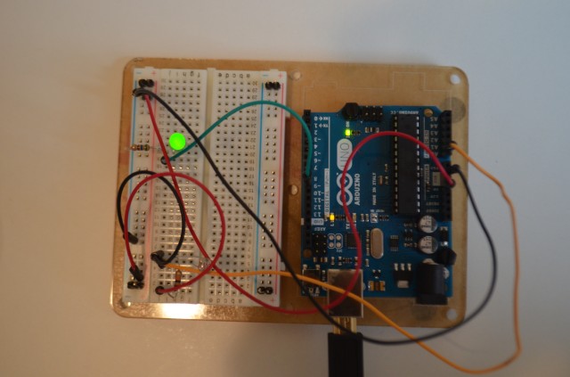
I feel like I should make a “Great Gatsby” joke about the green light but that’s not pertinent

IMG_2227

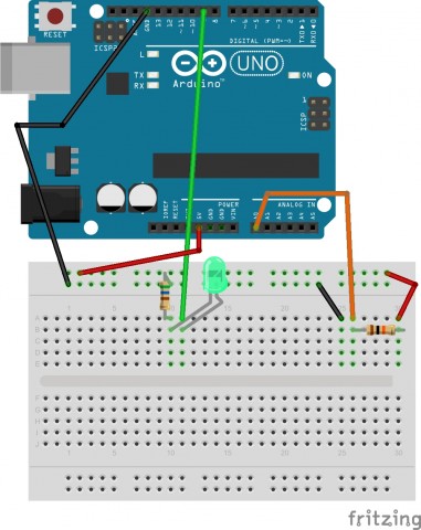
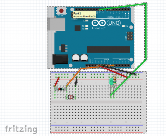
#9

this is a really unpleasant-to-look-at fritzing diagram I’m sorry I need to get used to using the program better

the code comes from the web address given in the instruction booklet:

/*
 * A simple programme that will change the intensity of
 * an LED based  * on the amount of light incident on 
 * the photo resistor.
 * 
 */

//PhotoResistor Pin
int lightPin = 0; //the analog pin the photoresistor is 
                  //connected to
                  //the photoresistor is not calibrated to any units so
                  //this is simply a raw sensor value (relative light)
//LED Pin
int ledPin = 9;   //the pin the LED is connected to
                  //we are controlling brightness so 
                  //we use one of the PWM (pulse width
                  // modulation pins)
void setup()
{
  pinMode(ledPin, OUTPUT); //sets the led pin to output
}
 /*
 * loop() - this function will start after setup 
 * finishes and then repeat
 */
void loop()
{
 int lightLevel = analogRead(lightPin); //Read the
                                        // lightlevel
 lightLevel = map(lightLevel, 0, 900, 0, 255); 
         //adjust the value 0 to 900 to
         //span 0 to 255


 lightLevel = constrain(lightLevel, 0, 255);//make sure the 
                                           //value is betwween 
                                           //0 and 255
 analogWrite(ledPin, lightLevel);  //write the value
}

Photoresistor

IMG_0108Irresistible.

photoresistor_bbb


/*
 * A simple programme that will change the intensity of
 * an LED based  * on the amount of light incident on 
 * the photo resistor.
 * 
 */

//PhotoResistor Pin
int lightPin = 0; //the analog pin the photoresistor is 
                  //connected to
                  //the photoresistor is not calibrated to any units so
                  //this is simply a raw sensor value (relative light)
//LED Pin
int ledPin = 9;   //the pin the LED is connected to
                  //we are controlling brightness so 
                  //we use one of the PWM (pulse width
                  // modulation pins)
void setup()
{
  pinMode(ledPin, OUTPUT); //sets the led pin to output
}
 /*
 * loop() - this function will start after setup 
 * finishes and then repeat
 */
void loop()
{
 int lightLevel = analogRead(lightPin); //Read the
                                        // lightlevel
 lightLevel = map(lightLevel, 0, 900, 0, 255); 
         //adjust the value 0 to 900 to
         //span 0 to 255


 lightLevel = constrain(lightLevel, 0, 255);//make sure the 
                                           //value is betwween 
                                           //0 and 255
 analogWrite(ledPin, lightLevel);  //write the value
}

Photoresistor

Youtube Video

https://www.youtube.com/watch?v=uNPaaZP4_Yo

Final Photo

DSC_0003

Fritzing Diagram

Screen Shot 2014-10-22 at 12.08.04 PM

The Source Code

/*
 * A simple programme that will change the intensity of
 * an LED based  * on the amount of light incident on 
 * the photo resistor.
 * 
 */

//PhotoResistor Pin
int lightPin = 0; //the analog pin the photoresistor is 
                  //connected to
                  //the photoresistor is not calibrated to any units so
                  //this is simply a raw sensor value (relative light)
//LED Pin
int ledPin = 9;   //the pin the LED is connected to
                  //we are controlling brightness so 
                  //we use one of the PWM (pulse width
                  // modulation pins)
void setup()
{
  pinMode(ledPin, OUTPUT); //sets the led pin to output
}
 /*
 * loop() - this function will start after setup 
 * finishes and then repeat
 */
void loop()
{
 int lightLevel = analogRead(lightPin); //Read the
                                        // lightlevel
 lightLevel = map(lightLevel, 0, 900, 0, 255); 
         //adjust the value 0 to 900 to
         //span 0 to 255


 lightLevel = constrain(lightLevel, 0, 255);//make sure the 
                                           //value is betwween 
                                           //0 and 255
 analogWrite(ledPin, lightLevel);  //write the value
}

Looking Outwards- you better bet I’m gonna make something that lights up all fancy

You know it’s true. I’m gonna do it. I actually already have a super cool idea that’s probably overly complicated but I’m gonna tell you about it. Well, sort of. There’s two versions. I hope nobody minds that I’m going to talk about three different interesting sensors and add-ons that I found because they’re all super cool.

First one: Flora Color Sensor (https://www.adafruit.com/product/1356)

Flora Color Sensor with White Illumination LED - TCS34725

I like the Flora doodads because they’re tiny (this one’s about the size of a nickel) and meant to be sewn into or onto things. Uses for it individually: since it’s color-sensitive, you could use it in tandem with pretty much anything else and make devices that allow blind or colorblind people to find color-matching outfits? I actually just came up with that off the top of my head; this one’s kind of hard to use on its own, but I have ideas down below in the post that incorporate it.

Second: Adafruit NeoPixel Shield (https://www.adafruit.com/products/1430)

Adafruit NeoPixel Shield for Arduino - 40 RGB LED Pixel Matrix

This is a really cool thing that lets you customize all 40 of these tiny RGB LEDs from one single pin, which is super cool, and also I love colors. This is the main part of both my cool ideas that I talk about later. Anyway, how else this could be used independently is as a color readout of pretty much any data; it could be programmed to visually represent numerical data, sound, temperature, video game health bars, pretty much whatever you can think of.

and Third: MP3 player shield (https://www.sparkfun.com/products/10628)
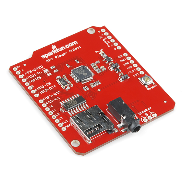
MP3 Player Shield

this one’s pretty basic; you put MP3s on a micro SD card and plug it into the shield, and then the MP3 files can be used somehow to interact with the Arduino. I’m not entirely clear on how it works because I’m not super well versed in digital music stuff.

how to use these things:

The first idea is pretty simple- take color input from the Flora Color sensor and send it to the LED shield, so the LEDs display a tiny lit-up version of whatever colors the sensor is seeing. I have no idea if there’s a practical application for this or not, but it’s cute.

The other idea is to use the MP3 player Shield and the RGB LED shield in tandem to essentially create a synesthetic output generator. Presuming I’m right about how it works, I could use the MP3 input to generate a specific color output depending on what music is being inputted. I think that would involve writing a program to analyze the quality of the MP3s themselves though, and I have no idea how complex that’d be or if that’s even a thing that’s possible.

Written by Comments Off on Looking Outwards- you better bet I’m gonna make something that lights up all fancy Posted in LookingOutwards

Looking Outwards – Will Taylor

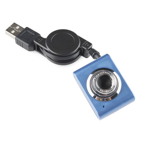
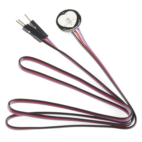
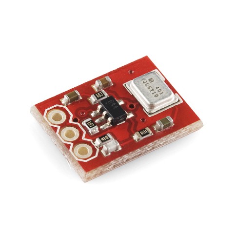
While browsing Sparkfun and Adafruit, I began thinking about different combinations of sensors I could use in a project. The webcam, pulse sensor, and microphone stood out as a good trio for me. I think it would be very interesting to have audio and visual data for situations in which a person becomes stressed, aroused, or extremely relaxed. The focus doesn’t necessarily have to be on the person whose pulse is being recorded. Perhaps the webcam and microphone is in a separate location, but will not be activated until the participant reaches a relaxed, meditative state. I would definitely want to make the project about relaxation, because in today’s fast-paced lifestyle it’s become harder to get into a calm state of mind.

Webcam:

webcam


Pulse Sensor:

Pulse Sensor

Microphone:

Microphone


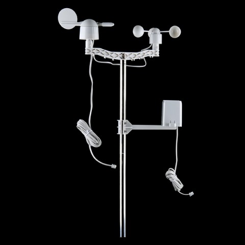
On a separate note, one sensor that really stood out to me was the weather sensor. It’s really cool that technology has reached the point where these can be manufactured so inexpensively. I’d like to use this sensor in an interactive installation or sculpture that would change in accordance with the weather outside.

Weather sensor:

Weather meters

Written by Comments Off on Looking Outwards – Will Taylor Posted in LookingOutwards

Looking outwards- Arduino Parts

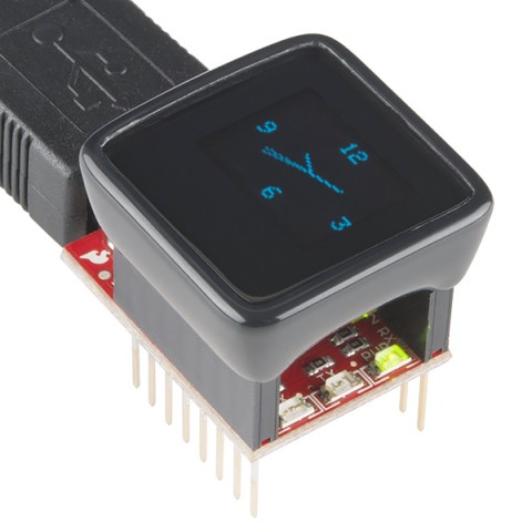
MicroView by Geek Ammo

12924-03

There are so many different fancy gadgets for the Arduino, but this one stuck out to me as something that would help me as I get the gist of physical computing and as a visual person. The MicroView would be great for rapid prototyping, being able to see real time what the Arduino is thinking without connecting it to your computer (no serial port or usb cables). I could use it for displaying what would normally be displayed on my laptop, defiantly icing for project that requires graphics and mobility. This could be used to collect data from people popcorn style from off the street. It has a development board with an PMOLED (passive matrix organic light emitting diode) screen that can be programmed, and can do anything that an Arduino pro can do.

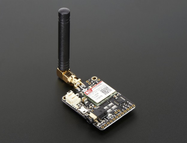
FONA by Ada fruit

adafruit_products_1963_demo_iso_ORIG

FONA has a GSM cellular module that can send and receive voice, text, SMS and data. Using FONA has two major advantages in my view. First, I can use FONA to send and receive data from the physical world, not like an actual phone would. Any information that can be collected by an Arduino can be distributed, for example, in an interactive installation a person can have their “results” texted to them. This allows more privacy, or to get the  “special treatment” feel. Second, FONA is a cheaper and way easier alternative to buying a crappy phone and trying to work through that, also, alternatively, I wouldn’t have to use my own phone number in this hypothetical installation. To put it super broadly, I can build my own phone and let that give me freedom to do whatever I need to do.

Photoresistor

IMG_1034

Photoresistor_bb

/*
 * A simple programme that will change the intensity of
 * an LED based  * on the amount of light incident on 
 * the photo resistor.
 * 
 */

//PhotoResistor Pin
int lightPin = 0; //the analog pin the photoresistor is 
                  //connected to
                  //the photoresistor is not calibrated to any units so
                  //this is simply a raw sensor value (relative light)
//LED Pin
int ledPin = 9;   //the pin the LED is connected to
                  //we are controlling brightness so 
                  //we use one of the PWM (pulse width
                  // modulation pins)
void setup()
{
  pinMode(ledPin, OUTPUT); //sets the led pin to output
}
 /*
 * loop() - this function will start after setup 
 * finishes and then repeat
 */
void loop()
{
 int lightLevel = analogRead(lightPin); //Read the
                                        // lightlevel
 lightLevel = map(lightLevel, 0, 900, 0, 255); 
         //adjust the value 0 to 900 to
         //span 0 to 255


 lightLevel = constrain(lightLevel, 0, 255);//make sure the 
                                           //value is between 
                                           //0 and 255
 analogWrite(ledPin, lightLevel);  //write the value
}