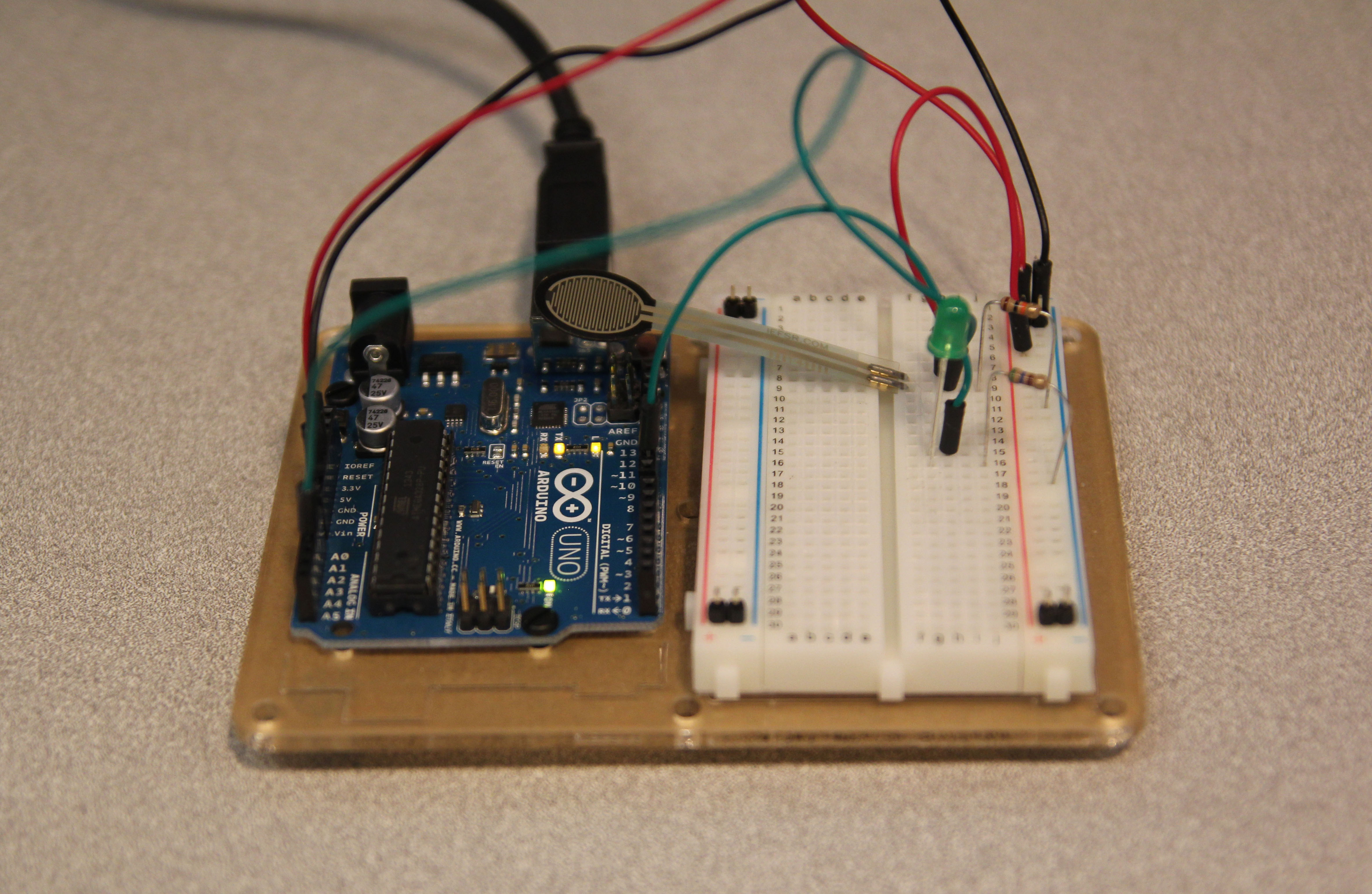
Circuit 13: Squeezing

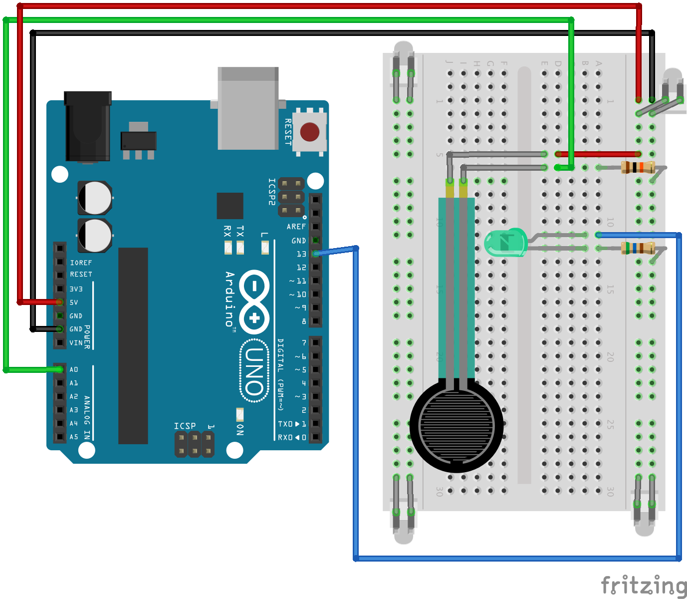
Circuit 13CIRC13 Fritzing Diagram_bb

/*
 * Force Sensitive Resistor Test Code
 *
 * The intensity of the LED will vary with the amount of pressure on the sensor
 */

int sensePin = 2;    // the pin the FSR is attached to
int ledPin = 9;      // the pin the LED is attached to (use one capable of PWM)

void setup() {
  Serial.begin(9600);
  pinMode(ledPin, OUTPUT);  // declare the ledPin as an OUTPUT
}

void loop() {
  int value = analogRead(sensePin) / 4; //the voltage on the pin divded by 4 (to scale from 10 bits (0-1024) to 8 (0-255)
  analogWrite(ledPin, value);        //sets the LEDs intensity proportional to the pressure on the sensor
  Serial.println(value);              //print the value to the debug window
}

Circuit 10: Temperature

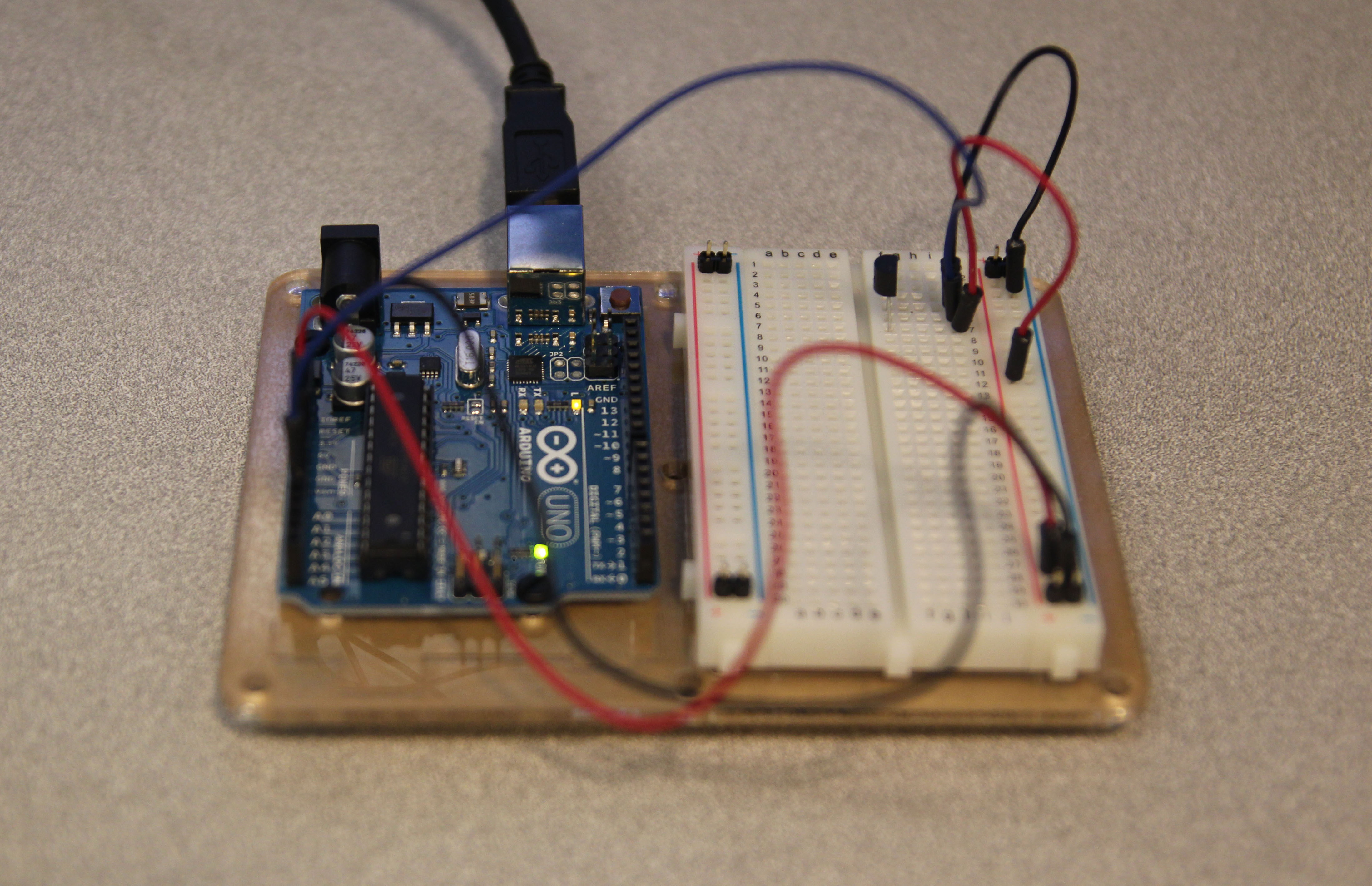
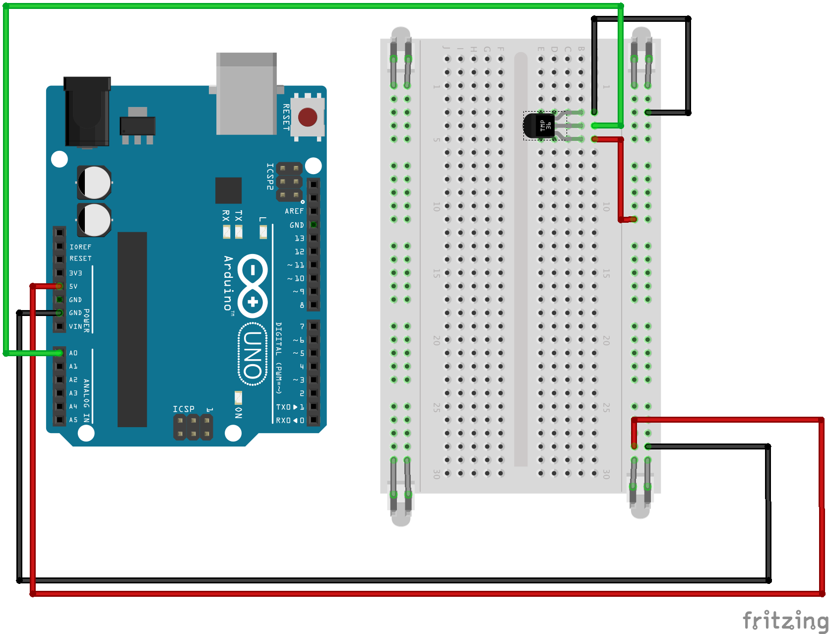
Circuit 10CIRC10 Fritzing Diagram_bb

/*     ---------------------------------------------------------
 *     |  Arduino Experimentation Kit Example Code             |
 *     |  CIRC-10 .: Temperature :. (TMP36 Temperature Sensor) |
 *     ---------------------------------------------------------
 *   
 *  A simple program to output the current temperature to the IDE's debug window 
 * 
 *  For more details on this circuit: http://tinyurl.com/c89tvd 
 */

//TMP36 Pin Variables
int temperaturePin = 0; //the analog pin the TMP36's Vout (sense) pin is connected to
                        //the resolution is 10 mV / degree centigrade 
                        //(500 mV offset) to make negative temperatures an option

/*
 * setup() - this function runs once when you turn your Arduino on
 * We initialize the serial connection with the computer
 */
void setup()
{
  Serial.begin(9600);  //Start the serial connection with the copmuter
                       //to view the result open the serial monitor 
                       //last button beneath the file bar (looks like a box with an antenae)
}
 
void loop()                     // run over and over again
{
 float temperature = getVoltage(temperaturePin);  //getting the voltage reading from the tem
                    //perature sensor
 temperature = (temperature - .5) * 100;          //converting from 10 mv per degree wit 500
                    // mV offset
                                                  //to degrees ((volatge - 500mV) times 100)
 Serial.println(temperature);                     //printing the result
 delay(1000);                                     //waiting a second
}

/*
 * getVoltage() - returns the voltage on the analog input defined by
 * pin
 */
float getVoltage(int pin){
 return (analogRead(pin) * .004882814); //converting from a 0 to 1023 digital range
                                        // to 0 to 5 volts (each 1 reading equals ~ 5 milliv
                    //olts
}

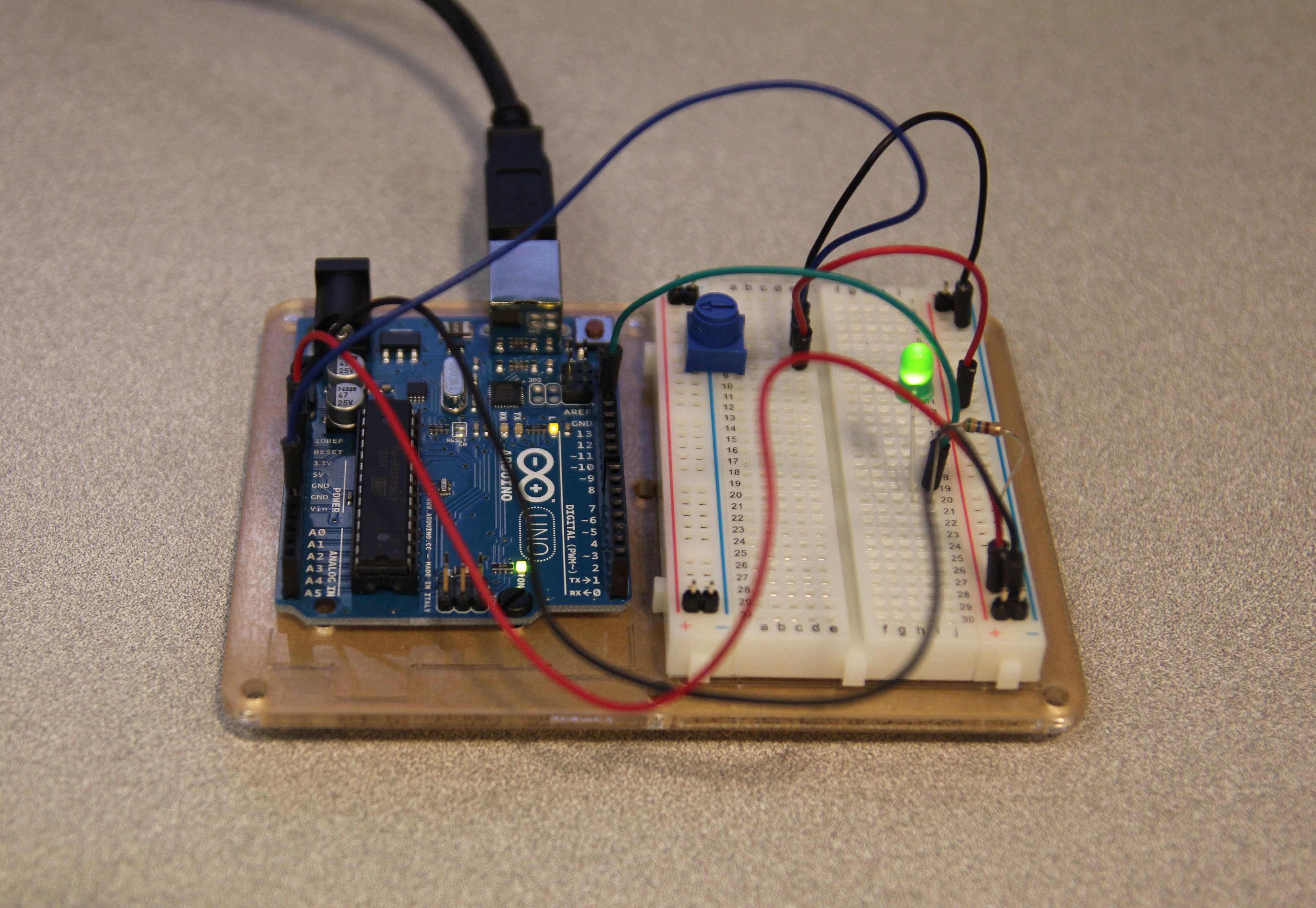
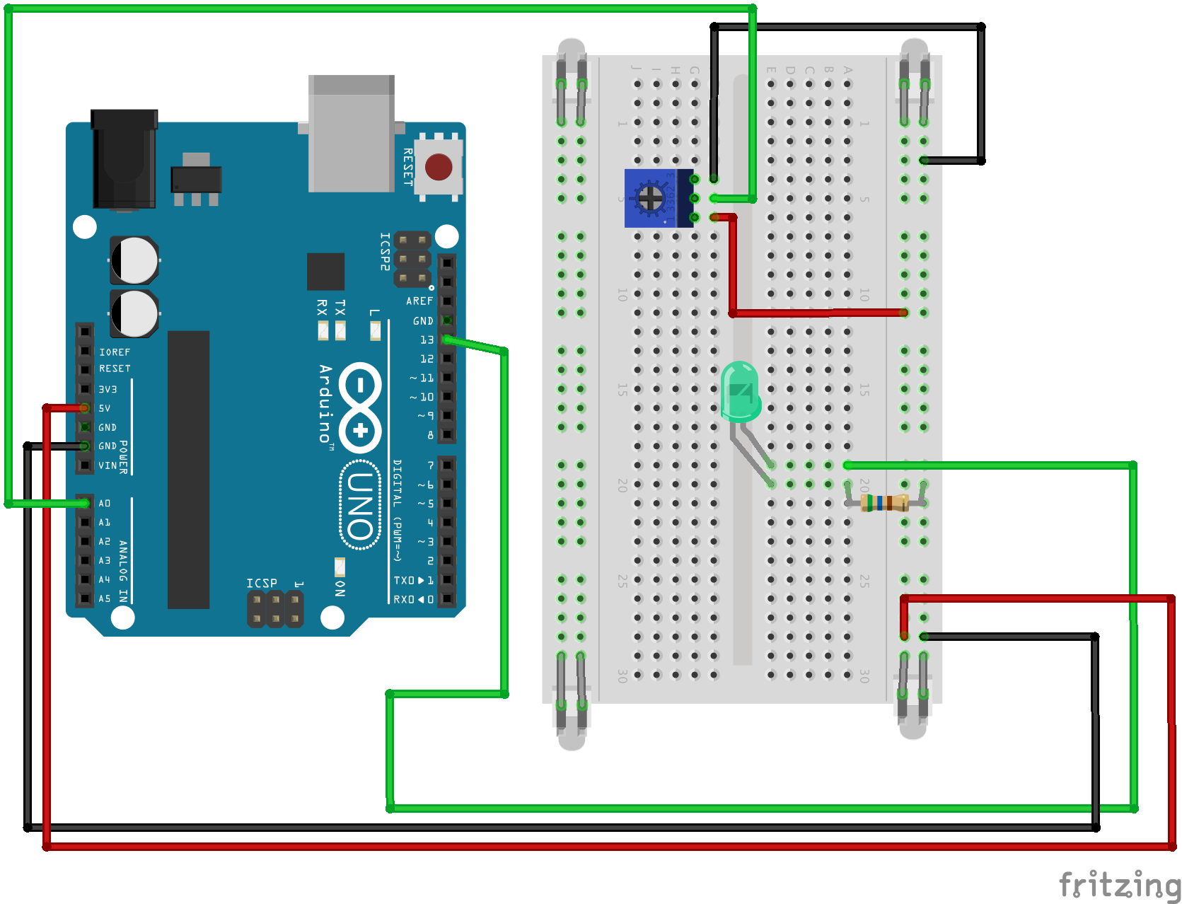
Circuit 8: Potentiometer

Circuit 8CIRC8 Fritzing Diagram_bb

/*
  Analog Input
 Demonstrates analog input by reading an analog sensor on analog pin 0 and
 turning on and off a light emitting diode(LED)  connected to digital pin 13. 
 The amount of time the LED will be on and off depends on
 the value obtained by analogRead(). 
 
 The circuit:
 * Potentiometer attached to analog input 0
 * center pin of the potentiometer to the analog pin
 * one side pin (either one) to ground
 * the other side pin to +5V
 * LED anode (long leg) attached to digital output 13
 * LED cathode (short leg) attached to ground
 
 * Note: because most Arduinos have a built-in LED attached 
 to pin 13 on the board, the LED is optional.
 
 
 Created by David Cuartielles
 modified 30 Aug 2011
 By Tom Igoe
 
 This example code is in the public domain.
 
 http://arduino.cc/en/Tutorial/AnalogInput
 
 */

int sensorPin = A0;    // select the input pin for the potentiometer
int ledPin = 13;      // select the pin for the LED
int sensorValue = 0;  // variable to store the value coming from the sensor

void setup() {
  // declare the ledPin as an OUTPUT:
  pinMode(ledPin, OUTPUT);  
}

void loop() {
  // read the value from the sensor:
  sensorValue = analogRead(sensorPin);    
  // turn the ledPin on
  digitalWrite(ledPin, HIGH);  
  // stop the program for  milliseconds:
  delay(sensorValue);          
  // turn the ledPin off:        
  digitalWrite(ledPin, LOW);   
  // stop the program for for  milliseconds:
  delay(sensorValue);                  
}

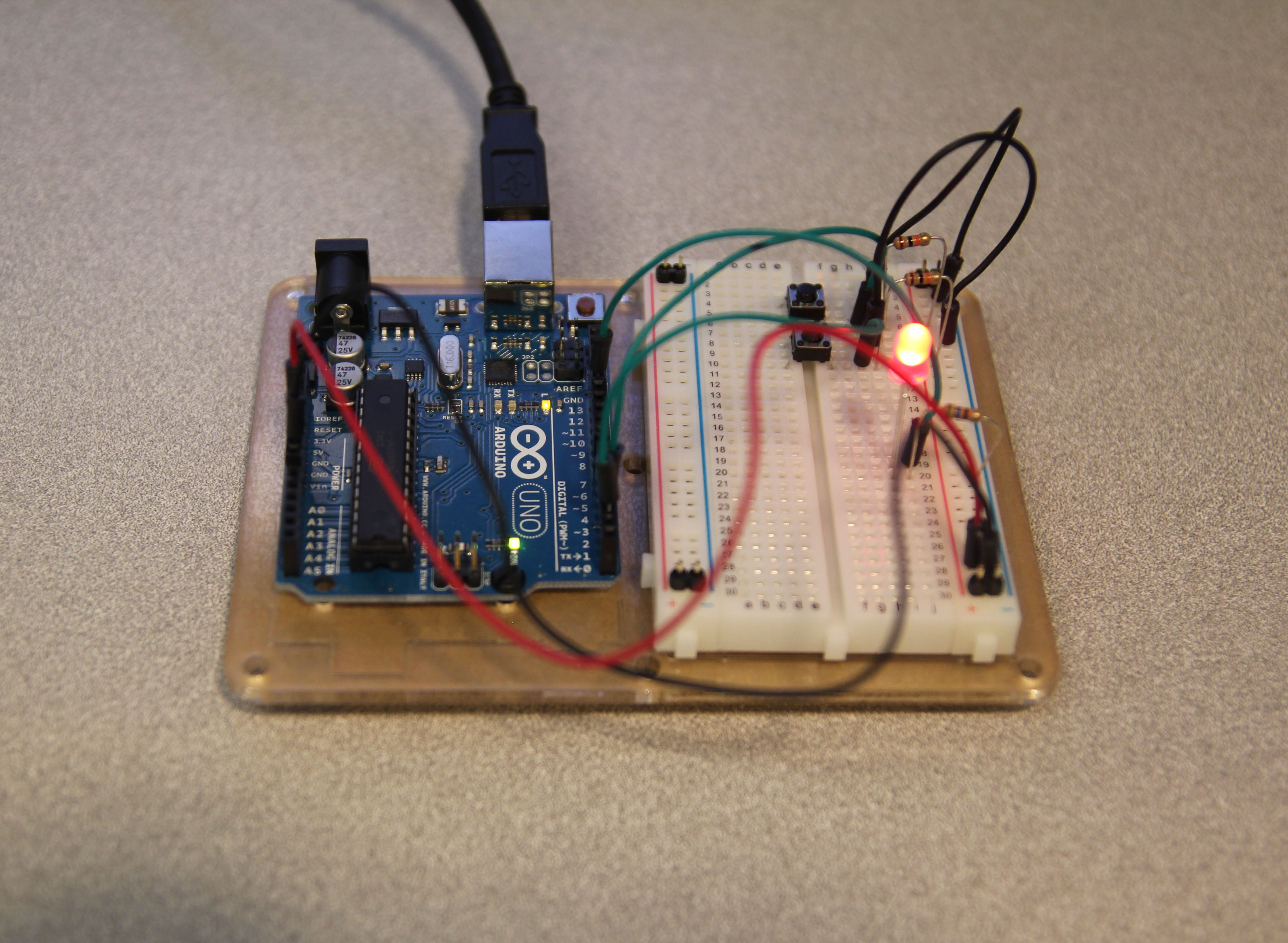
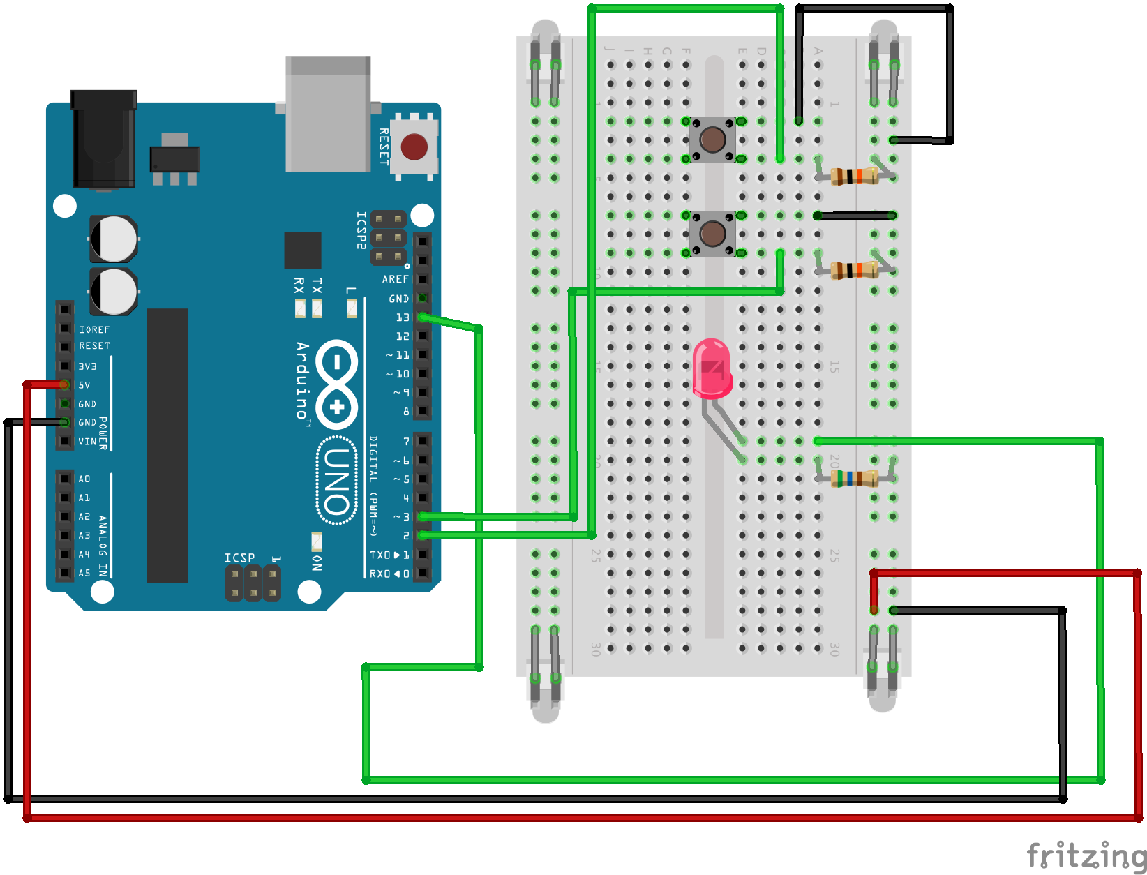
Circuit 7: Pushbuttons

Circuit 7CIRC7 Fritzing Diagram_bb

int ledPin = 13; // choose the pin for the LED
int inputPin1 = 3; // button 1
int inputPin2 = 2; // button 2
 
void setup() {
  pinMode(ledPin, OUTPUT); // declare LED as output
  pinMode(inputPin1, INPUT); // make button 1 an input
  pinMode(inputPin2, INPUT); // make button 2 an input
}
 
void loop(){
  if (digitalRead(inputPin1) == LOW) {
    digitalWrite(ledPin, LOW); // turn LED OFF
  } else if (digitalRead(inputPin2) == LOW) {
    digitalWrite(ledPin, HIGH); // turn LED ON
  }
} 

Circuit #9: Photoresistor

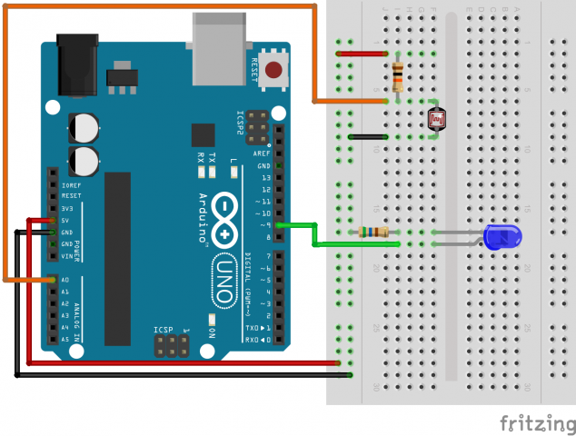
IMG_1990

Screen Shot 2014-10-22 at 5.45.23 PM

/*
 * A simple programme that will change the intensity of
 * an LED based  * on the amount of light incident on 
 * the photo resistor.
 * 
 */

//PhotoResistor Pin
int lightPin = 0; //the analog pin the photoresistor is 
                  //connected to
                  //the photoresistor is not calibrated to any units so
                  //this is simply a raw sensor value (relative light)
//LED Pin
int ledPin = 9;   //the pin the LED is connected to
                  //we are controlling brightness so 
                  //we use one of the PWM (pulse width
                  // modulation pins)
void setup()
{
  pinMode(ledPin, OUTPUT); //sets the led pin to output
}
 /*
 * loop() - this function will start after setup 
 * finishes and then repeat
 */
void loop()
{
 int lightLevel = analogRead(lightPin); //Read the
                                        // lightlevel
 lightLevel = map(lightLevel, 0, 900, 0, 255); 
         //adjust the value 0 to 900 to
         //span 0 to 255


 lightLevel = constrain(lightLevel, 0, 255);//make sure the 
                                           //value is betwween 
                                           //0 and 255
 analogWrite(ledPin, lightLevel);  //write the value
}

Adafruit 9-DOF IMU Breakout

This is a combination accelerometer, gyroscope, and magnetometer. It is noted as acceptable for motion tracking. I could possibly use this in some type of motion tracked object such as an instrument that is played by music, or a device that uses motion to decide how to play music. I could make a ball that always lights an led that is on the top of the ball. I could make an object which screams when it is falling by having it know when no gravity or little force is present (as in during a freefall). I could make an object that vomits when it is dizzy by using the rotational sensing from the gyro. I could make a robot that is scared of magnets and runs from them. The possibilities for a 9DOF IMU are endless. I think it would be most interesting to make a small bot that screams when falling, runs from magnets, and vomits when it gets dizzy. To me this is interesting because running from fears, screaming, and getting nauseated are very human things to do which makes it odd and unnecessary for a robot to do them. This would be one step closer to robots with feelings or Skynet.

9DOF

VCNL4000 Proximity/Light sensor

This is a proximity sensor for small distances. I imagine using it for making different tones based on how far your hand is held over it. It could also be incorporated in a light which turns on when your hand is near it, but changes hue based on how close your hand gets to it. It could also be incorporated with an electromagnet to accomplish levitation. The magnet is strengthened when the object is too far, and weakened when it is too close. The two ideas together would be interesting to me because levitation is amazing, but levitation projects I’ve seen don’t incorporate interactivity.
proximity_sensor

Continue reading

[S]ensored.

11195-01

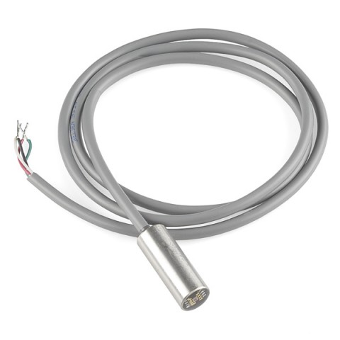
RGB Color Detecting Sensor

This sensor sends RGB values of the light it receives to it’s output wires. While the power of light on it’s own is a very useful measurement to have the type of light that is being input is even more powerful. While I am not exactly sure what I would want to do with this piece it definitely would not be difficult to map the red, green and blue values of light in a room to sound, other lights and power distributed to a room. This one stood out, from the other sensors but I’m not exactly sure why.

1063-00

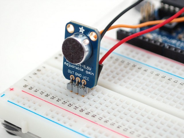
Electret Microphone Amiplifier

1064-00

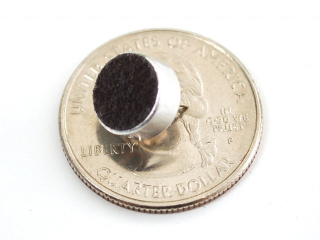
Electret Microphone

This amplifier is a great way to translate both direct and ambient sound into data which I can process with my arduino. I love sound and being able to couple sound with the portability and computational abilities of the arduino would be fantastic. I have a few ideas for projects which would involve analyzing the sounds I make on a normal basis (Whether that be with my voice or otherwise). In particular I would like to match audio levels to some kind of physical reaction on my body.

Looking Outwards- Arduino Parts

Colour Sensor:

light_1356demo_LRG.

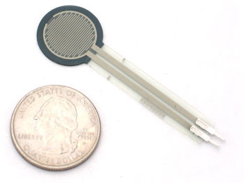
Force Sensitive Resistor (FSR) :

force___flex_FSR402_MED

I like the idea of triggering reactions through touch and pressure, as well as colour. Our associations to certain colours can help reflect an object in the state of dormancy as well as liveliness, and touch has the possibility of creating an object ( or creature-like object) react in certain ways. I think if I were to create an arduino-based piece, I would like to create something which reacts specifically to the difference nuances of human touch.

Photo-resistor? Photo-resistor!

A video of the photo-resistor working for your viewing pleaure.

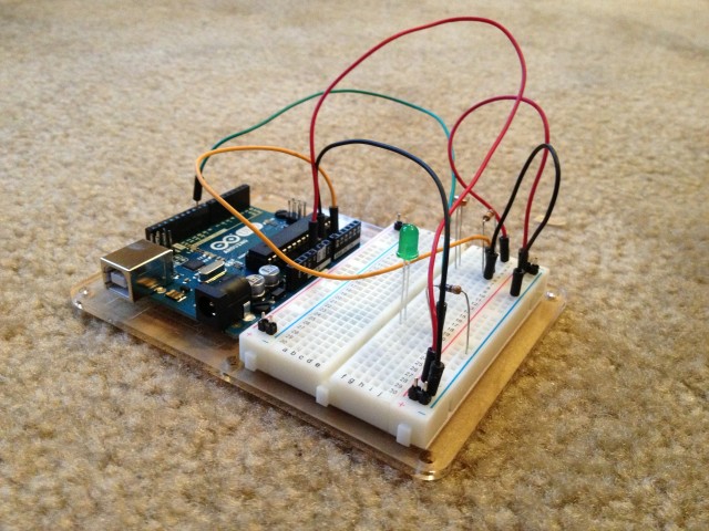
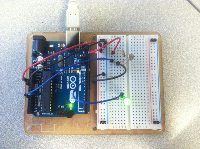
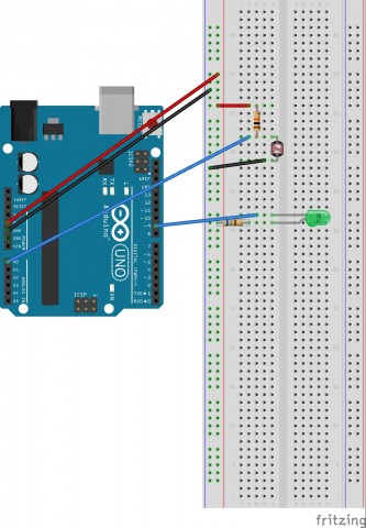
A photograph of my finished product.
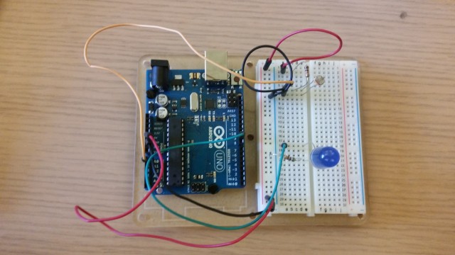
20141022_164417

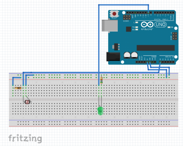
A “Fritzing” Diagram of my circuit.

PhotoFritzLuca

Source code for the project. The code below was taken from

ARDX.org

/*
 * A simple programme that will change the intensity of
 * an LED based  * on the amount of light incident on 
 * the photo resistor.
 * 
 */

//PhotoResistor Pin
int lightPin = 0; //the analog pin the photoresistor is 
                  //connected to
                  //the photoresistor is not calibrated to any units so
                  //this is simply a raw sensor value (relative light)
//LED Pin
int ledPin = 9;   //the pin the LED is connected to
                  //we are controlling brightness so 
                  //we use one of the PWM (pulse width
                  // modulation pins)
void setup()
{
  pinMode(ledPin, OUTPUT); //sets the led pin to output
}
 /*
 * loop() - this function will start after setup 
 * finishes and then repeat
 */
void loop()
{
 int lightLevel = analogRead(lightPin); //Read the
                                        // lightlevel
 lightLevel = map(lightLevel, 0, 900, 0, 255); 
         //adjust the value 0 to 900 to
         //span 0 to 255


 lightLevel = constrain(lightLevel, 0, 255);//make sure the 
                                           //value is between 
                                           //0 and 255
 analogWrite(ledPin, lightLevel);  //write the value
}
Photoresistor Alex

photo-2


Photosense_bb


/*
 * A simple programme that will change the intensity of
 * an LED based  * on the amount of light incident on 
 * the photo resistor.
 * 
 */

//PhotoResistor Pin
int lightPin = 0; //the analog pin the photoresistor is 
                  //connected to
                  //the photoresistor is not calibrated to any units so
                  //this is simply a raw sensor value (relative light)
//LED Pin
int ledPin = 9;   //the pin the LED is connected to
                  //we are controlling brightness so 
                  //we use one of the PWM (pulse width
                  // modulation pins)
void setup()
{
  pinMode(ledPin, OUTPUT); //sets the led pin to output
}
 /*
 * loop() - this function will start after setup 
 * finishes and then repeat
 */
void loop()
{
 int lightLevel = analogRead(lightPin); //Read the
                                        // lightlevel
 lightLevel = map(lightLevel, 0, 900, 0, 255); 
         //adjust the value 0 to 900 to
         //span 0 to 255


 lightLevel = constrain(lightLevel, 0, 255);//make sure the 
                                           //value is betwween 
                                           //0 and 255
 analogWrite(ledPin, lightLevel);  //write the value
}