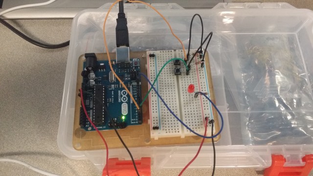
Assignment 10A _Push Buttons

https://www.youtube.com/watch?v=Ab6Lca6MGD8&feature=youtu.be

20141022_191434CIRC-07


/*
  Button
 
 Turns on and off a light emitting diode(LED) connected to digital  
 pin 13, when pressing a pushbutton attached to pin 7. 
 
 
 The circuit:
 * LED attached from pin 13 to ground 
 * pushbutton attached to pin 2 from +5V
 * 10K resistor attached to pin 2 from ground
 
 * Note: on most Arduinos there is already an LED on the board
 attached to pin 13.
 
 
 created 2005
 by DojoDave 
 modified 17 Jun 2009
 by Tom Igoe
 
  http://www.arduino.cc/en/Tutorial/Button
 */
 
// constants won't change. They're used here to 
// set pin numbers:
const int buttonPin = 2;     // the number of the pushbutton pin
const int ledPin =  13;      // the number of the LED pin
 
// variables will change:
int buttonState = 0;         // variable for reading the pushbutton status
 
void setup() {
  // initialize the LED pin as an output:
  pinMode(ledPin, OUTPUT);      
  // initialize the pushbutton pin as an input:
  pinMode(buttonPin, INPUT);     
}
 
void loop(){
  // read the state of the pushbutton value:
  buttonState = digitalRead(buttonPin);
 
  // check if the pushbutton is pressed.
  // if it is, the buttonState is HIGH:
  if (buttonState == HIGH) {     
    // turn LED on:    
    digitalWrite(ledPin, HIGH);  
  } 
  else {
    // turn LED off:
    digitalWrite(ledPin, LOW); 
  }
}
Written by Comments Off on Assignment 10A _Push Buttons Posted in Assignment-10A

Assignment-10B : Potentiometers


potentiometer


/*
  Analog Input
 Demonstrates analog input by reading an analog sensor on analog pin 0 and
 turning on and off a light emitting diode(LED)  connected to digital pin 13. 
 The amount of time the LED will be on and off depends on
 the value obtained by analogRead(). 
 
 The circuit:
 * Potentiometer attached to analog input 0
 * center pin of the potentiometer to the analog pin
 * one side pin (either one) to ground
 * the other side pin to +5V
 * LED anode (long leg) attached to digital output 13
 * LED cathode (short leg) attached to ground
 
 * Note: because most Arduinos have a built-in LED attached 
 to pin 13 on the board, the LED is optional.
 
 
 Created by David Cuartielles
 Modified 16 Jun 2009
 By Tom Igoe
 
 http://arduino.cc/en/Tutorial/AnalogInput
 
 */

int sensorPin = 0;    // select the input pin for the potentiometer
int ledPin = 13;      // select the pin for the LED
int sensorValue = 0;  // variable to store the value coming from the sensor

void setup() {
  // declare the ledPin as an OUTPUT:
  pinMode(ledPin, OUTPUT);  
}

void loop() {
  // read the value from the sensor:
  sensorValue = analogRead(sensorPin);    
  // turn the ledPin on
  digitalWrite(ledPin, HIGH);  
  // stop the program for  milliseconds:
  delay(sensorValue);          
  // turn the ledPin off:        
  digitalWrite(ledPin, LOW);   
  // stop the program for for  milliseconds:
  delay(sensorValue);                  
}

Assignment- 10A : Push Buttons

pushbuttons


/*
  Button
 
 Turns on and off a light emitting diode(LED) connected to digital  
 pin 13, when pressing a pushbutton attached to pin 7. 
 
 
 The circuit:
 * LED attached from pin 13 to ground 
 * pushbutton attached to pin 2 from +5V
 * 10K resistor attached to pin 2 from ground
 
 * Note: on most Arduinos there is already an LED on the board
 attached to pin 13.
 
 
 created 2005
 by DojoDave 
 modified 17 Jun 2009
 by Tom Igoe
 
  http://www.arduino.cc/en/Tutorial/Button
 */

// constants won't change. They're used here to 
// set pin numbers:
const int buttonPin = 2;     // the number of the pushbutton pin
const int ledPin =  13;      // the number of the LED pin

// variables will change:
int buttonState = 0;         // variable for reading the pushbutton status

void setup() {
  // initialize the LED pin as an output:
  pinMode(ledPin, OUTPUT);      
  // initialize the pushbutton pin as an input:
  pinMode(buttonPin, INPUT);     
}

void loop(){
  // read the state of the pushbutton value:
  buttonState = digitalRead(buttonPin);

  // check if the pushbutton is pressed.
  // if it is, the buttonState is HIGH:
  if (buttonState == HIGH) {     
    // turn LED on:    
    digitalWrite(ledPin, HIGH);  
  } 
  else {
    // turn LED off:
    digitalWrite(ledPin, LOW); 
  }
}
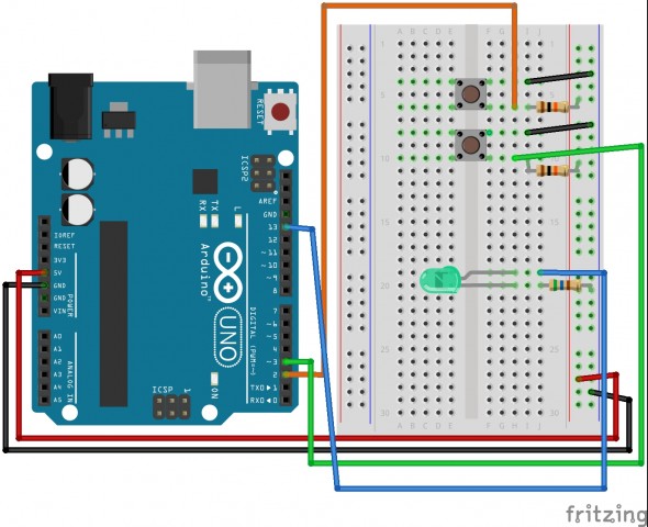
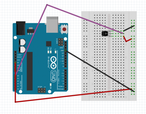
Circuit 10

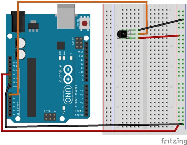
Circuit 10 :

Fritzing:

circut10The Code:

/*     ---------------------------------------------------------
 *     |  Arduino Experimentation Kit Example Code             |
 *     |  CIRC-10 .: Temperature :. (TMP36 Temperature Sensor) |
 *     ---------------------------------------------------------
 *   
 *  A simple program to output the current temperature to the IDE's debug window 
 * 
 *  For more details on this circuit: http://tinyurl.com/c89tvd 
 */

//TMP36 Pin Variables
int temperaturePin = 0; //the analog pin the TMP36's Vout (sense) pin is connected to
                        //the resolution is 10 mV / degree centigrade 
                        //(500 mV offset) to make negative temperatures an option

/*
 * setup() - this function runs once when you turn your Arduino on
 * We initialize the serial connection with the computer
 */
void setup()
{
  Serial.begin(9600);  //Start the serial connection with the copmuter
                       //to view the result open the serial monitor 
                       //last button beneath the file bar (looks like a box with an antenae)
}
 
void loop()                     // run over and over again
{
 float temperature = getVoltage(temperaturePin);  //getting the voltage reading from the temperature sensor
 temperature = (temperature - .5) * 100;          //converting from 10 mv per degree wit 500 mV offset
                                                  //to degrees ((volatge - 500mV) times 100)
 Serial.println(temperature);                     //printing the result
 delay(1000);                                     //waiting a second
}

/*
 * getVoltage() - returns the voltage on the analog input defined by
 * pin
 */
float getVoltage(int pin){
 return (analogRead(pin) * .004882814); //converting from a 0 to 1023 digital range
                                        // to 0 to 5 volts (each 1 reading equals ~ 5 millivolts
}

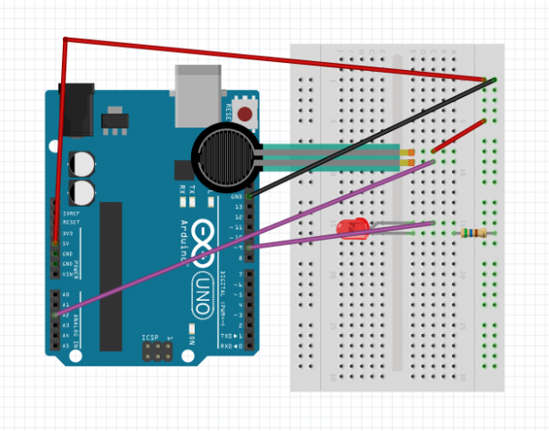
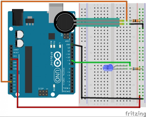
Assignment 10B- Squeezing

Screen Shot 2014-10-27 at 20.28.48


/*
 * Force Sensitive Resistor Test Code
 *
 * The intensity of the LED will vary with the amount of pressure on the sensor
 */

int sensePin = 2;    // the pin the FSR is attached to
int ledPin = 9;      // the pin the LED is attached to (use one capable of PWM)

void setup() {
  Serial.begin(9600);
  pinMode(ledPin, OUTPUT);  // declare the ledPin as an OUTPUT
}

void loop() {
  int value = analogRead(sensePin) / 4; //the voltage on the pin divded by 4 (to scale from 10 bits (0-1024) to 8 (0-255)
  analogWrite(ledPin, value);        //sets the LEDs intensity proportional to the pressure on the sensor
  Serial.println(value);              //print the value to the debug window
}

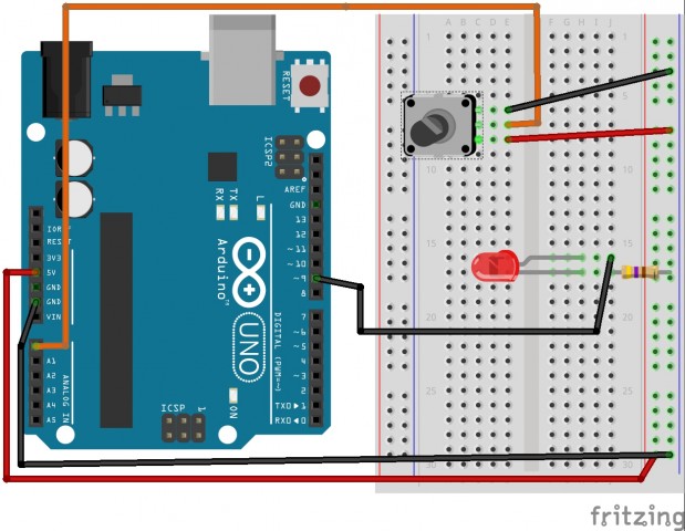
Circuit 8 & 13

Circuit 8:

Circuit 13:

Fritzing:

circut8

circut13

Code:

/*
  Analog Input
 Demonstrates analog input by reading an analog sensor on analog pin 0 and
 turning on and off a light emitting diode(LED)  connected to digital pin 13. 
 The amount of time the LED will be on and off depends on
 the value obtained by analogRead(). 
 
 The circuit:
 * Potentiometer attached to analog input 0
 * center pin of the potentiometer to the analog pin
 * one side pin (either one) to ground
 * the other side pin to +5V
 * LED anode (long leg) attached to digital output 13
 * LED cathode (short leg) attached to ground
 
 * Note: because most Arduinos have a built-in LED attached 
 to pin 13 on the board, the LED is optional.
 
 
 Created by David Cuartielles
 Modified 16 Jun 2009
 By Tom Igoe
 
 http://arduino.cc/en/Tutorial/AnalogInput
 
 */

int sensorPin = 0;    // select the input pin for the potentiometer
int ledPin = 13;      // select the pin for the LED
int sensorValue = 0;  // variable to store the value coming from the sensor

void setup() {
  // declare the ledPin as an OUTPUT:
  pinMode(ledPin, OUTPUT);  
}

void loop() {
  // read the value from the sensor:
  sensorValue = analogRead(sensorPin);    
  // turn the ledPin on
  digitalWrite(ledPin, HIGH);  
  // stop the program for  milliseconds:
  delay(sensorValue);          
  // turn the ledPin off:        
  digitalWrite(ledPin, LOW);   
  // stop the program for for  milliseconds:
  delay(sensorValue);                  
}
////comment that code ^ and uncomment this code for circuit 13
//int sensePin = 2; // the pin the FSR is attached to
//int ledPin = 9; // the pin the LED is attached to (use one capable of PWM)
//void setup() {
// Serial.begin(9600);
// pinMode(ledPin, OUTPUT); // declare the ledPin as an OUTPUT
//}
//void loop() {
// int value = analogRead(sensePin) / 4; //the voltage on the pin divded by 4 (to 
// //scale from 10 bits (0-1024) to 8 (0-255)
// analogWrite(ledPin, value); //sets the LEDs intensity proportional to 
// //the pressure on the sensor
// Serial.println(value); //print the value to the debug window
//}


Assignment 10C- Temperature


Screen Shot 2014-10-27 at 20.15.02

/*     ---------------------------------------------------------
 *     |  Arduino Experimentation Kit Example Code             |
 *     |  CIRC-10 .: Temperature :. (TMP36 Temperature Sensor) |
 *     ---------------------------------------------------------
 *   
 *  A simple program to output the current temperature to the IDE's debug window 
 * 
 *  For more details on this circuit: http://tinyurl.com/c89tvd 
 */

//TMP36 Pin Variables
int temperaturePin = 0; //the analog pin the TMP36's Vout (sense) pin is connected to
                        //the resolution is 10 mV / degree centigrade 
                        //(500 mV offset) to make negative temperatures an option

/*
 * setup() - this function runs once when you turn your Arduino on
 * We initialize the serial connection with the computer
 */
void setup()
{
  Serial.begin(9600);  //Start the serial connection with the copmuter
                       //to view the result open the serial monitor 
                       //last button beneath the file bar (looks like a box with an antenae)
}
 
void loop()                     // run over and over again
{
 float temperature = getVoltage(temperaturePin);  //getting the voltage reading from the tem
                    //perature sensor
 temperature = (temperature - .5) * 100;          //converting from 10 mv per degree wit 500
                    // mV offset
                                                  //to degrees ((volatge - 500mV) times 100)
 Serial.println(temperature);                     //printing the result
 delay(1000);                                     //waiting a second
}

/*
 * getVoltage() - returns the voltage on the analog input defined by
 * pin
 */
float getVoltage(int pin){
 return (analogRead(pin) * .004882814); //converting from a 0 to 1023 digital range
                                        // to 0 to 5 volts (each 1 reading equals ~ 5 milliv
                    //olts
}

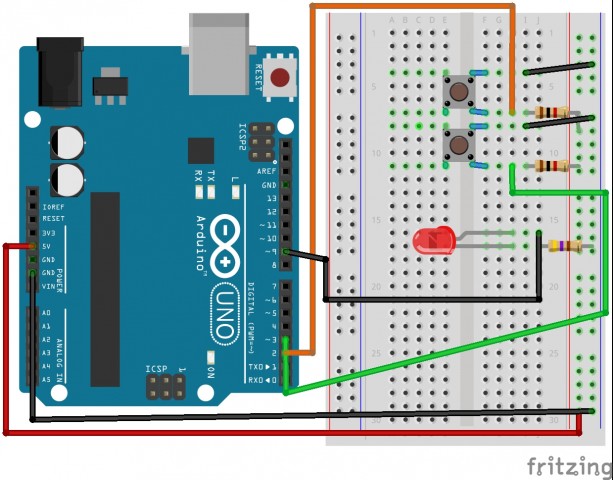
Circuit 7

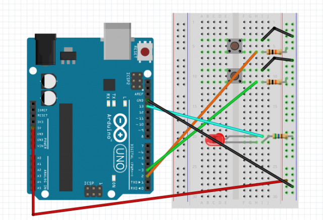
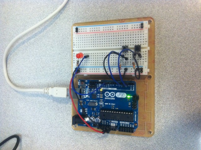
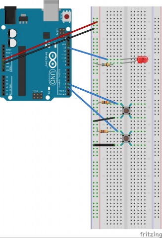
This is the first part of the LED working with one button:

This is the second part (under “make it better”) of the LED controlled by two buttons:

Third part (also under “make it better”) of the LED being faded by the two buttons:

Fritzing diagram:

circut7
The Code:

/*
/*
* Button
* by DojoDave <http://www.0j0.org>
*
* Turns on and off a light emitting diode(LED) connected to digital
* pin 13, when pressing a pushbutton attached to pin 7.
* http://www.arduino.cc/en/Tutorial/Button
*/
int ledPin = 13; // choose the pin for the LED
int inputPin = 2; // choose the input pin (for a pushbutton)
int val = 0; // variable for reading the pin status
void setup() {
pinMode(ledPin, OUTPUT); // declare LED as output
pinMode(inputPin, INPUT); // declare pushbutton as input
}
void loop(){
val = digitalRead(inputPin); // read input value
if (val == HIGH) { // check if the input is HIGH
digitalWrite(ledPin, LOW); // turn LED OFF
} else {
digitalWrite(ledPin, HIGH); // turn LED ON
}
}


// //comment out the previous code and uncomment this for the second part

//int ledPin = 13; // choose the pin for the LED
//int inputPin1 = 3; // button 1
//int inputPin2 = 2; // button 2

//void setup() {
//  pinMode(ledPin, OUTPUT); // declare LED as output
//  pinMode(inputPin1, INPUT); // make button 1 an input
// pinMode(inputPin2, INPUT); // make button 2 an input
//}

//void loop(){

// if (digitalRead(inputPin1) == LOW) {
//    digitalWrite(ledPin, LOW); // turn LED OFF
// } else if (digitalRead(inputPin2) == LOW) {
//    digitalWrite(ledPin, HIGH); // turn LED ON /

////for part three comment the entire loop function and uncomment this , and then //change the input pin from 13 to 9

////int value = 0;
////void loop(){
//// if (digitalRead(inputPin1) == LOW) { value--; }
////  else if (digitalRead(inputPin2) == LOW) { value++; }
////  value = constrain(value, 0, 255);
////  analogWrite(ledPin, value);
////  delay(10);
////}

//  }
//}


Button

photo 2


Button


  Button
 
 Turns on and off a light emitting diode(LED) connected to digital  
 pin 13, when pressing a pushbutton attached to pin 7. 
 
 
 The circuit:
 * LED attached from pin 13 to ground 
 * pushbutton attached to pin 2 from +5V
 * 10K resistor attached to pin 2 from ground
 
 * Note: on most Arduinos there is already an LED on the board
 attached to pin 13.
 
 
 created 2005
 by DojoDave 
 modified 17 Jun 2009
 by Tom Igoe
 
  http://www.arduino.cc/en/Tutorial/Button
 */

// constants won't change. They're used here to 
// set pin numbers:
const int buttonPin = 2;     // the number of the pushbutton pin
const int ledPin =  13;      // the number of the LED pin

// variables will change:
int buttonState = 0;         // variable for reading the pushbutton status

void setup() {
  // initialize the LED pin as an output:
  pinMode(ledPin, OUTPUT);      
  // initialize the pushbutton pin as an input:
  pinMode(buttonPin, INPUT);     
}

void loop(){
  // read the state of the pushbutton value:
  buttonState = digitalRead(buttonPin);

  // check if the pushbutton is pressed.
  // if it is, the buttonState is HIGH:
  if (buttonState == HIGH) {     
    // turn LED on:    
    digitalWrite(ledPin, HIGH);  
  } 
  else {
    // turn LED off:
    digitalWrite(ledPin, LOW); 
  }
}
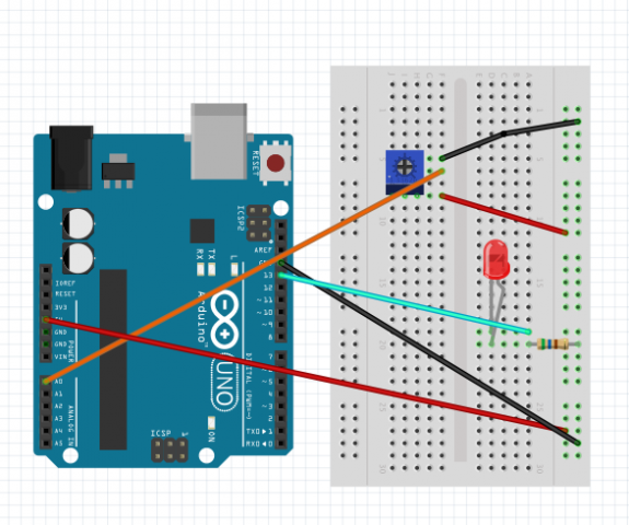
Looking Outwards: Sensors and Shields

Adafruit Color Sensors

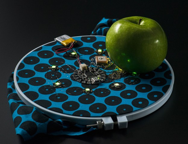
I found this particular sensor to be extremely exciting because I am really interested in color theory. One of the projects I was thinking of was a simple matching game when an individual would see a color on a screen, out of reach, and try and match that color exactly using an assortment of objects around them. I would also enjoy using this sensor for my own personal painting practice in order to discover interesting color combinations.

light_1356demo_LRG


Flex Sensor 2.2

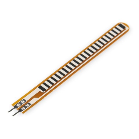
For this sensor, I thought it would be interesting in performance pieces. I really would enjoy being able to use the movements of my body to control sound and visuals. These would either have to be built into cloths or somehow hidden under makeup because I think it would be physically interesting to have someones face being able to control these elements as well and not just through a camera lens. I wounded how sensitive these sensors are.

https://www.sparkfun.com/products/10264

10264-01