Assignment-10B: Variable Resistors (Circuits 08 & 13)

Assignment-10B: Variable Resistors (Circuits 08 & 13)

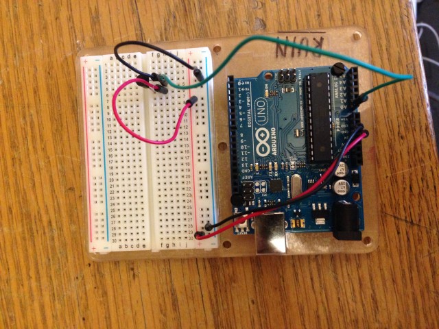
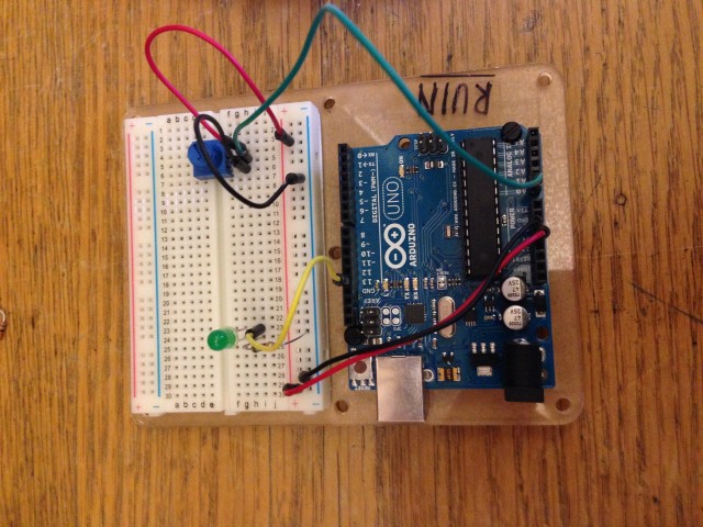
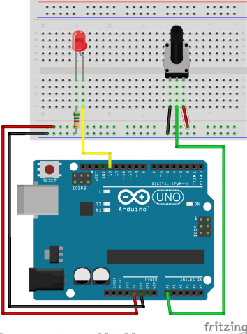
(Circuit 08) setup: (Circuit 08)


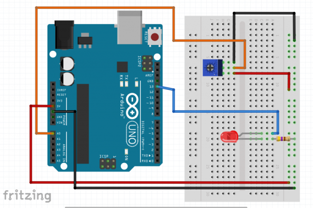
diagram diagram

Code:

Analog Input
Demonstrates analog input by reading an analog sensor on analog pin 0 and
turning on and off a light emitting diode(LED) connected to digital pin 13.
The amount of time the LED will be on and off depends on
the value obtained by analogRead().
The circuit:
* Potentiometer attached to analog input 0
* center pin of the potentiometer to the analog pin
* one side pin (either one) to ground
* the other side pin to +5V
* LED anode (long leg) attached to digital output 13
* LED cathode (short leg) attached to ground

* Note: because most Arduinos have a built-in LED attached
to pin 13 on the board, the LED is optional.

Created by David Cuartielles
Modified 16 Jun 2009
By Tom Igoe

http://arduino.cc/en/Tutorial/AnalogInput

*/

int sensorPin = 0; // select the input pin for the potentiometer
int ledPin = 13; // select the pin for the LED
int sensorValue = 0; // variable to store the value coming from the sensor

void setup() {
// declare the ledPin as an OUTPUT:
pinMode(ledPin, OUTPUT);
}

void loop() {
// read the value from the sensor:
sensorValue = analogRead(sensorPin);
// turn the ledPin on
digitalWrite(ledPin, HIGH);
// stop the program for milliseconds:
delay(sensorValue);
// turn the ledPin off:
digitalWrite(ledPin, LOW);
// stop the program for for milliseconds:
delay(sensorValue);
}

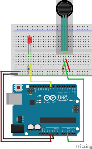
Circuit 13:
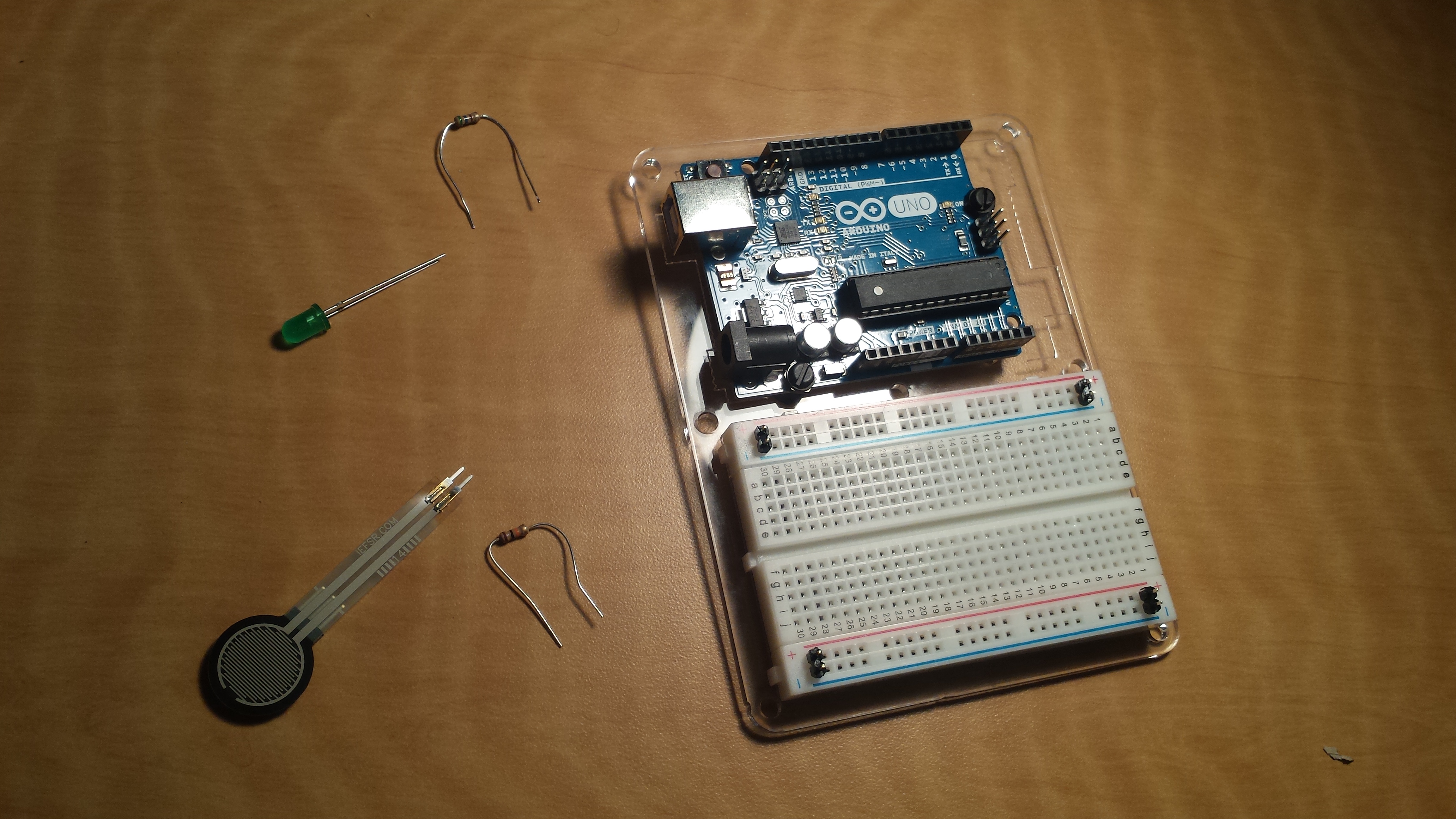
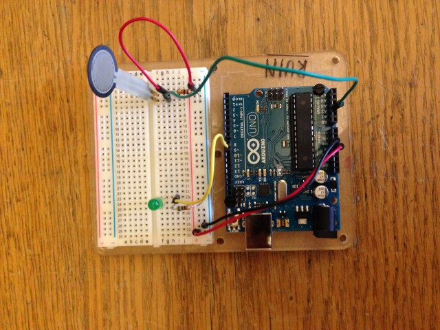
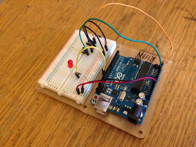
Project 13 setup: (Circuit 13)

In action:

pro13

diagram diagram

Code:


/*
/*
 * Force Sensitive Resistor Test Code
 *
 * The intensity of the LED will vary with the amount of pressure on the sensor
 */

int sensePin = 2;    // the pin the FSR is attached to
int ledPin = 9;      // the pin the LED is attached to (use one capable of PWM)

void setup() {
  Serial.begin(9600);
  pinMode(ledPin, OUTPUT);  // declare the ledPin as an OUTPUT
}

void loop() {
  int value = analogRead(sensePin) / 4; //the voltage on the pin divded by 4 (to scale from 10 bits (0-1024) to 8 (0-255)
  analogWrite(ledPin, value);        //sets the LEDs intensity proportional to the pressure on the sensor
  Serial.println(value);              //print the value to the debug window
}
Written by Comments Off on Assignment-10B: Variable Resistors (Circuits 08 & 13) Posted in Assignment-10B

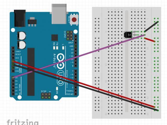
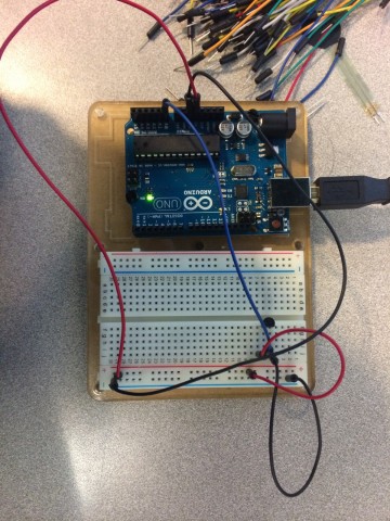
circuit 10

video
IMG_0149 (2)

MOV_5968 (2)

picture
IMG_0149 (2)

fritzing
Screen Shot 2014-10-30 at 6.53.08 PM

code

/*     ---------------------------------------------------------
 *     |  Arduino Experimentation Kit Example Code             |
 *     |  CIRC-10 .: Temperature :. (TMP36 Temperature Sensor) |
 *     ---------------------------------------------------------
 *   
 *  A simple program to output the current temperature to the IDE's debug window 
 * 
 *  For more details on this circuit: http://tinyurl.com/c89tvd 
 */

//TMP36 Pin Variables
int temperaturePin = 0; //the analog pin the TMP36's Vout (sense) pin is connected to
                        //the resolution is 10 mV / degree centigrade 
                        //(500 mV offset) to make negative temperatures an option

/*
 * setup() - this function runs once when you turn your Arduino on
 * We initialize the serial connection with the computer
 */
void setup()
{
  Serial.begin(9600);  //Start the serial connection with the copmuter
                       //to view the result open the serial monitor 
                       //last button beneath the file bar (looks like a box with an antenae)
}
 
void loop()                     // run over and over again
{
 float temperature = getVoltage(temperaturePin);  //getting the voltage reading from the temperature sensor
 temperature = (temperature - .5) * 100;          //converting from 10 mv per degree wit 500 mV offset
                                                  //to degrees ((volatge - 500mV) times 100)
 Serial.println(temperature);                     //printing the result
 delay(1000);                                     //waiting a second
}

/*
 * getVoltage() - returns the voltage on the analog input defined by
 * pin
 */
float getVoltage(int pin){
 return (analogRead(pin) * .004882814); //converting from a 0 to 1023 digital range
                                        // to 0 to 5 volts (each 1 reading equals ~ 5 millivolts
}

Circuit 08/13

video
MOV_6319 (1)

picture
IMG_0149 (1)

fritzing diagram
Screen Shot 2014-10-30 at 6.53.00 PM

code
/*
  Analog Input
 Demonstrates analog input by reading an analog sensor on analog pin 0 and
 turning on and off a light emitting diode(LED)  connected to digital pin 13. 
 The amount of time the LED will be on and off depends on
 the value obtained by analogRead(). 
 
 The circuit:
 * Potentiometer attached to analog input 0
 * center pin of the potentiometer to the analog pin
 * one side pin (either one) to ground
 * the other side pin to +5V
 * LED anode (long leg) attached to digital output 13
 * LED cathode (short leg) attached to ground
 
 * Note: because most Arduinos have a built-in LED attached 
 to pin 13 on the board, the LED is optional.
 
 
 Created by David Cuartielles
 modified 30 Aug 2011
 By Tom Igoe
 
 This example code is in the public domain.
 
 http://arduino.cc/en/Tutorial/AnalogInput
 
 */

int sensorPin = A0;    // select the input pin for the potentiometer
int ledPin = 13;      // select the pin for the LED
int sensorValue = 0;  // variable to store the value coming from the sensor

void setup() {
  // declare the ledPin as an OUTPUT:
  pinMode(ledPin, OUTPUT);  
}

void loop() {
  // read the value from the sensor:
  sensorValue = analogRead(sensorPin);    
  // turn the ledPin on
  digitalWrite(ledPin, HIGH);  
  // stop the program for <sensorValue> milliseconds:
  delay(sensorValue);          
  // turn the ledPin off:        
  digitalWrite(ledPin, LOW);   
  // stop the program for for <sensorValue> milliseconds:
  delay(sensorValue);                  
}

Assignment 10: Temperature Sensor

IMG_1089

Thermistor_bb

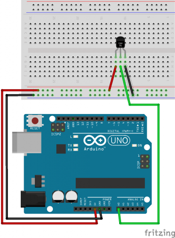
int temperaturePin = 0;

void setup()
{
  Serial.begin(9600);  //Start the serial connection with the copmuter
                       //to view the result open the serial monitor 
                       //last button beneath the file bar (looks like a box with an antenae)
}
 
void loop()                     // run over and over again
{
 float temperature = getVoltage(temperaturePin);  //getting the voltage reading from the tem
                    //perature sensor
 temperature = (temperature - .5) * 100;          //converting from 10 mv per degree wit 500
                    // mV offset
                                                  //to degrees ((volatge - 500mV) times 100)
 Serial.println(temperature);                     //printing the result
 delay(1000);                                     //waiting a second
}

/*
 * getVoltage() - returns the voltage on the analog input defined by
 * pin
 */
float getVoltage(int pin){
 return (analogRead(pin) * .004882814); //converting from a 0 to 1023 digital range
                                        // to 0 to 5 volts (each 1 reading equals ~ 5 milliv
                    //olts
}


Assignment 10: Variable Resistors

Twisting Variable Resistor

IMG_1085

TwistingPotentiometer_bb

int sensorPin = 0;    // select the input pin for the potentiometer
int ledPin = 13;      // select the pin for the LED
int sensorValue = 0;  // variable to store the value coming from the sensor

void setup() {
  // declare the ledPin as an OUTPUT:
  pinMode(ledPin, OUTPUT);  
}

void loop() {
  // read the value from the sensor:
  sensorValue = analogRead(sensorPin);    
  // turn the ledPin on
  digitalWrite(ledPin, HIGH);  
  // stop the program for  milliseconds:
  delay(sensorValue);          
  // turn the ledPin off:        
  digitalWrite(ledPin, LOW);   
  // stop the program for for  milliseconds:
  delay(sensorValue);                  
}

FSR

IMG_1087

FSR_bb

int sensePin = 2;    // the pin the FSR is attached to
int ledPin = 9;      // the pin the LED is attached to (use one capable of PWM)

void setup() {
  Serial.begin(9600);
  pinMode(ledPin, OUTPUT);  // declare the ledPin as an OUTPUT
}

void loop() {
  int value = analogRead(sensePin) / 4; //the voltage on the pin divded by 4 (to scale from 10 bits (0-1024) to 8 (0-255)
  analogWrite(ledPin, value);        //sets the LEDs intensity proportional to the pressure on the sensor
  Serial.println(value);              //print the value to the debug window
}
 

Assignment 10: Pushbuttons

Unfortunately, I took no video. Use your imagination.

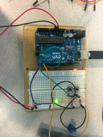
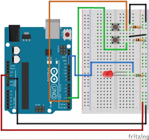
IMG_1084

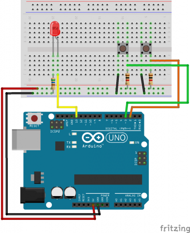
Buttons_bb

int ledPin = 13; // choose the pin for the LED 
int inputPin1 = 3; // button 1 
int inputPin2 = 2; // button 2 
  
void setup() { 
  pinMode(ledPin, OUTPUT); // declare LED as output 
  pinMode(inputPin1, INPUT); // make button 1 an input 
  pinMode(inputPin2, INPUT); // make button 2 an input 
} 
  
void loop(){ 
  if (digitalRead(inputPin1) == LOW) { 
    digitalWrite(ledPin, LOW); // turn LED OFF 
  } else if (digitalRead(inputPin2) == LOW) { 
    digitalWrite(ledPin, HIGH); // turn LED ON 
  } 
}


Circuit 07 clair

video of circuit 07
MOV_8733

picture of circuit 07
IMG_0221

fritzing diagram
circuit07

code
/*
Button

Turns on and off a light emitting diode(LED) connected to digital
pin 13, when pressing a pushbutton attached to pin 2.

 
 The circuit:
 * LED attached from pin 13 to ground 
 * pushbutton attached to pin 2 from +5V
 * 10K resistor attached to pin 2 from ground
 
 * Note: on most Arduinos there is already an LED on the board
 attached to pin 13.
 
 
 created 2005
 by DojoDave <http://www.0j0.org>
 modified 30 Aug 2011
 by Tom Igoe
 
 This example code is in the public domain.
 
 http://www.arduino.cc/en/Tutorial/Button
 */

// constants won't change. They're used here to 
// set pin numbers:
const int buttonPin = 2;     // the number of the pushbutton pin
const int ledPin =  13;      // the number of the LED pin

// variables will change:
int buttonState = 0;         // variable for reading the pushbutton status

void setup() {
  // initialize the LED pin as an output:
  pinMode(ledPin, OUTPUT);      
  // initialize the pushbutton pin as an input:
  pinMode(buttonPin, INPUT);     
}

void loop(){
  // read the state of the pushbutton value:
  buttonState = digitalRead(buttonPin);

  // check if the pushbutton is pressed.
  // if it is, the buttonState is HIGH:
  if (buttonState == HIGH) {     
    // turn LED on:    
    digitalWrite(ledPin, HIGH);  
  } 
  else {
    // turn LED off:
    digitalWrite(ledPin, LOW); 
  }
}

Circuit 4: A Single Servo

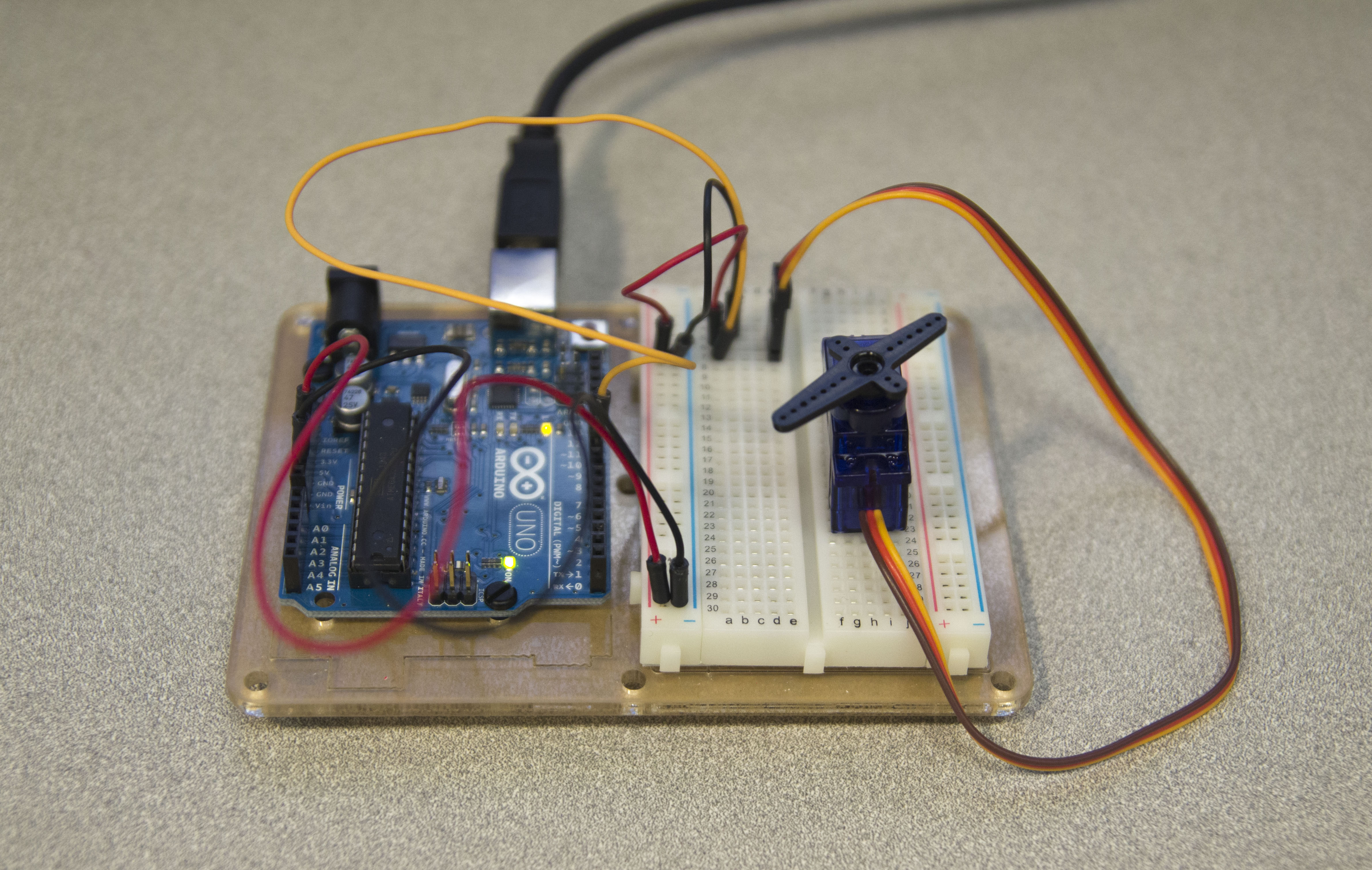
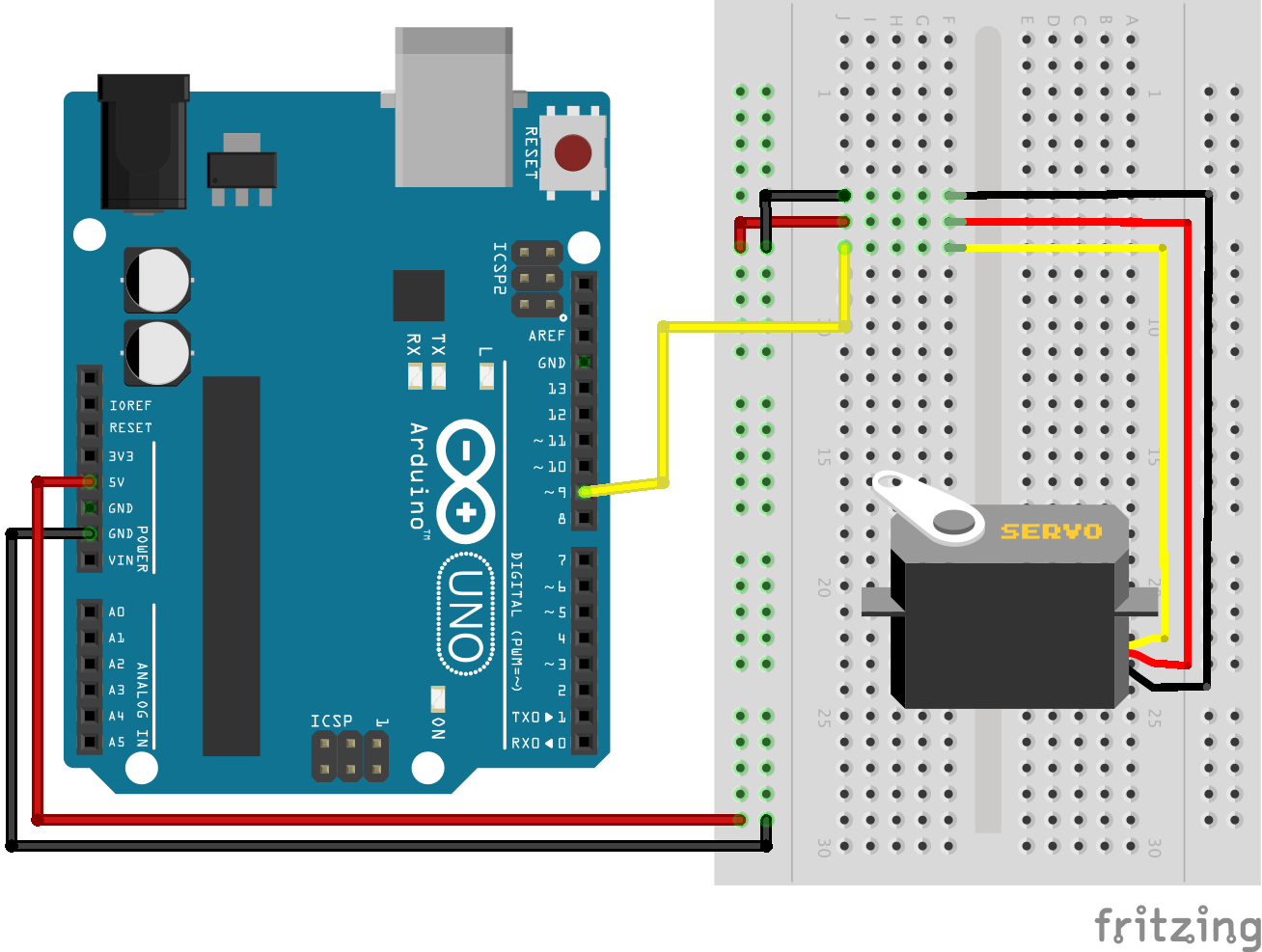
Circuit 4

Circuit 4_bb

/* Sweep
 by BARRAGAN  
 This example code is in the public domain.

 modified 8 Nov 2013
 by Scott Fitzgerald
 http://arduino.cc/en/Tutorial/Sweep
*/ 

#include  
 
Servo myservo;  // create servo object to control a servo 
                // twelve servo objects can be created on most boards
 
int pos = 0;    // variable to store the servo position 
 
void setup() 
{ 
  myservo.attach(9);  // attaches the servo on pin 9 to the servo object 
} 
 
void loop() 
{ 
  for(pos = 0; pos < = 180; pos += 1) // goes from 0 degrees to 180 degrees    {                                  // in steps of 1 degree      myservo.write(pos);              // tell servo to go to position in variable 'pos'      delay(15);                       // waits 15ms for the servo to reach the position    }    for(pos = 180; pos>=0; pos-=1)     // goes from 180 degrees to 0 degrees 
  {                                
    myservo.write(pos);              // tell servo to go to position in variable 'pos' 
    delay(15);                       // waits 15ms for the servo to reach the position 
  } 
} 

Circuit 3: Transistor & Motor

For some reason my motor appears to be get stuck. I can give it a twist manually to get it to go for a couple of rotations, but then it locks up again.

Circuit 3

Circuit 3_bb

/*     -----------------------------------------------------------
 *     |  Arduino Experimentation Kit Example Code               |
 *     |  CIRC-03 .: Spin Motor Spin :. (Transistor and Motor)   |
 *     -----------------------------------------------------------
 * 
 * The Arduinos pins are great for driving LEDs however if you hook 
 * up something that requires more power you will quickly break them.
 * To control bigger items we need the help of a transistor. 
 * Here we will use a transistor to control a small toy motor
 * 
 * http://tinyurl.com/d4wht7
 *
 */

int motorPin = 9;  // define the pin the motor is connected to
                   // (if you use pin 9,10,11 or 3you can also control speed)

/*
 * setup() - this function runs once when you turn your Arduino on
 * We set the motors pin to be an output (turning the pin high (+5v) or low (ground) (-))
 * rather than an input (checking whether a pin is high or low)
 */
void setup()
{
 pinMode(motorPin, OUTPUT); 
}


/*
 * loop() - this function will start after setup finishes and then repeat
 * we call a function called motorOnThenOff()
 */

void loop()                     // run over and over again
{
 motorOnThenOff();
 //motorOnThenOffWithSpeed();
 //motorAcceleration();
}

/*
 * motorOnThenOff() - turns motor on then off 
 * (notice this code is identical to the code we used for
 * the blinking LED)
 */
void motorOnThenOff(){
  int onTime = 2500;  //the number of milliseconds for the motor to turn on for
  int offTime = 1000; //the number of milliseconds for the motor to turn off for
  
  digitalWrite(motorPin, HIGH); // turns the motor On
  delay(onTime);                // waits for onTime milliseconds
  digitalWrite(motorPin, LOW);  // turns the motor Off
  delay(offTime);               // waits for offTime milliseconds
}

/*
 * motorOnThenOffWithSpeed() - turns motor on then off but uses speed values as well 
 * (notice this code is identical to the code we used for
 * the blinking LED)
 */
void motorOnThenOffWithSpeed(){
  
  int onSpeed = 200;  // a number between 0 (stopped) and 255 (full speed) 
  int onTime = 2500;  //the number of milliseconds for the motor to turn on for
  
  int offSpeed = 50;  // a number between 0 (stopped) and 255 (full speed) 
  int offTime = 1000; //the number of milliseconds for the motor to turn off for
  
  analogWrite(motorPin, onSpeed);   // turns the motor On
  delay(onTime);                    // waits for onTime milliseconds
  analogWrite(motorPin, offSpeed);  // turns the motor Off
  delay(offTime);                   // waits for offTime milliseconds
}

/*
 * motorAcceleration() - accelerates the motor to full speed then
 * back down to zero
*/
void motorAcceleration(){
  int delayTime = 50; //milliseconds between each speed step
  
  //Accelerates the motor
  for(int i = 0; i < 256; i++){ //goes through each speed from 0 to 255     analogWrite(motorPin, i);   //sets the new speed     delay(delayTime);           // waits for delayTime milliseconds   }      //Decelerates the motor   for(int i = 255; i >= 0; i--){ //goes through each speed from 255 to 0
    analogWrite(motorPin, i);   //sets the new speed
    delay(delayTime);           // waits for delayTime milliseconds
  }
}