Category Archives: 13-Parametric-Object

Celine Nguyen

23 Jan 2014

Computational Preoccupations with Vases
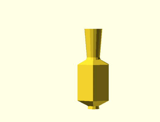
radius = 10; stemHeight = 20; stemBracketHeight = 5; bodyHeight = 20; elongation = 5;

radius = 10; stemHeight = 20; stemBracketHeight = 5; bodyHeight = 20; elongation = 5;

Summary

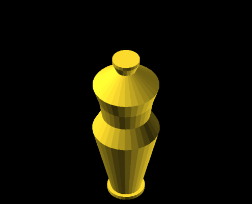
The faceted vase is an #openscad experiment by @mynameisceline to explore parametric polygonal decor.

Narrative

I chose to create something beautiful and useful. Vases have quite a bit of variety in form and structure and utility—the ongoing issue in my family every Mother’s Day is that my sister and I buy flowers that are too tall for a short vase, too short for a tall vase, too many for a slim vase, or too few for a wide vase. Clearly, the answer is parametric forms.

I’m also a huge fan of polygonal shapes (2D and 3D) in art and design. It so happens I have a pinboard full of polygonal inspiration:

Follow Celine Nguyen’s board Polygonal Geometries on Pinterest.

So. I made two initial sketches of polygonal vases (one with a faceted body and smoother stem, one with a faceted body and a curved inner cavity), but went with the first option to give me more customization/parameterization options. I’m pretty happy with how it turned out, since it’s reasonably changeable and I enjoy the different character that a tall/elegant vase and a small/squat vase convey.
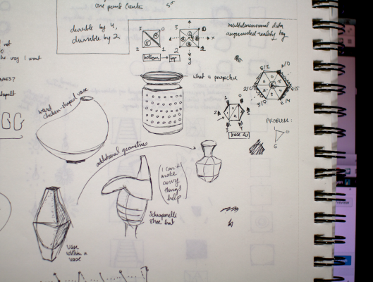
Sketches for parametric facet vase

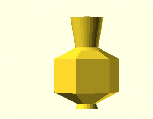
radius = 20; stemHeight = 20; stemBracketHeight = 2; bodyHeight = 20; elongation = 10;

radius = 20; stemHeight = 20; stemBracketHeight = 2; bodyHeight = 20; elongation = 10;

My initial sketch & vision for this called for the stem of the vase to be smoothly tapered and curved along the side (kind of like a conventional vase) to get a good contrast between the chunky/blocky part of the vase and a smoother, more delicate bit. I unfortunately couldn’t figure this out (although I spent some enjoyable time playing around with minkowski() and hull() in the attempt).
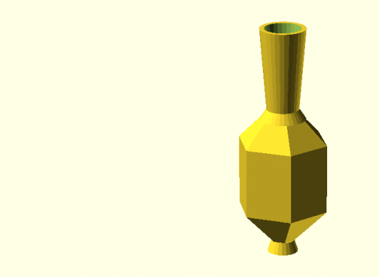
radius = 20; stemHeight = 40; stemBracketHeight = 5; bodyHeight = 30; elongation = 20;

radius = 20; stemHeight = 40; stemBracketHeight = 5; bodyHeight = 30; elongation = 20;

Code

(For some reason Thingiverse won’t finish processing my file uploads ; n ; ) 

+ Github repo.

// manipulable parameters!
radius = 10; // default: 10
stemHeight = 20; // default: 20
stemBracketHeight = 1; // default: 1
bodyHeight = 20; // default: 20
elongation = 5; // default: 8
 
// parameters i ask you not to touch
hollowThickness = 2;
opening = 4;
stemTopBase = radius / 2;
stemBottomBase = radius / 3;
 
// stem
translate([0, 0, elongation]){
	difference() {
		cylinder(h = stemHeight, r1 = stemBottomBase, r2 = stemTopBase, center = false);
		cylinder(h = stemHeight, r1 = stemBottomBase - hollowThickness, r2 = stemTopBase - hollowThickness, center = false);
	}
}
 
// stem bracket
translate([0, 0, 0]) {
	difference() {
		cylinder(h = elongation + stemBracketHeight, r1 = stemTopBase, r2 = stemBottomBase, center = false);
		cylinder(h = elongation + stemBracketHeight, r1 = stemTopBase - hollowThickness, r2 = stemBottomBase - hollowThickness, center = false);
	}
}
 
// top
translate([0, 0, 0]) {
difference() {
	polyhedron(
	  points = [[radius * 0.87, radius * 0.5, 0], // 0
	            [radius * 0, radius * 1, 0], // 1
	            [radius * -0.87, radius * 0.5, 0], // 2
	            [radius * -0.87, radius * -0.5, 0], // 3
	            [radius * 0, radius * -1, 0], // 4
	            [radius * 0.87, radius * -0.5, 0], // 5
	            [0, 0, elongation]], // the apex point, 6
	  triangles = [[0, 6, 1], [1, 6, 2], [2, 6, 3], [3, 6, 4], [4, 6, 5], [5, 6, 0], // sides
	               [0, 1, 3], [1, 2, 3], [0, 3, 4], [0, 4, 5]] // base
	 );
	cylinder(h = elongation, r1 = stemBottomBase - hollowThickness, r2 = stemTopBase - hollowThickness, center = false);
}
}
 
// body
translate([0, 0, -bodyHeight]) {
	difference() {
		linear_extrude(height = bodyHeight, center = false, convexity = 10) {
		  polygon(
	      points = [[radius * 0.87, radius * 0.5], // 0
	                [radius * 0, radius * 1], // 1
	                [radius * -0.87, radius * 0.5], // 2
	                [radius * -0.87, radius * -0.5], // 3
	                [radius * 0, radius * -1], // 4
	                [radius * 0.87, radius * -0.5]]
	    );
		}
		cylinder(h = bodyHeight, r1 = stemTopBase - hollowThickness, r2 = stemTopBase - hollowThickness, center = false);
	}
}
 
// bottom
translate([0, 0,  -bodyHeight]) {
	rotate(a = [0, 180, 0]) {
		polyhedron(
		  points = [[radius * 0.87, radius * 0.5, 0], // 0
		            [radius * 0, radius * 1, 0], // 1
		            [radius * -0.87, radius * 0.5, 0], // 2
		            [radius * -0.87, radius * -0.5, 0], // 3
		            [radius * 0, radius * -1, 0], // 4
		            [radius * 0.87, radius * -0.5, 0], // 5
		            [0, 0, elongation]], // the apex point, 6
		  triangles = [[0, 6, 1], [1, 6, 2], [2, 6, 3], [3, 6, 4], [4, 6, 5], [5, 6, 0], // sides
		               [0, 1, 3], [1, 2, 3], [0, 3, 4], [0, 4, 5]] // base
		 );
	}
}
 
// base
translate([0, 0,  -bodyHeight - elongation]){
	cylinder(h = 5, r1 = radius / 3, r2 = radius / 4, center = false);
}

Brandon Taylor

23 Jan 2014

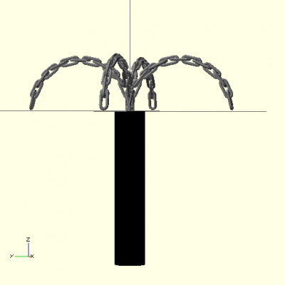
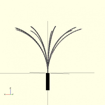
A customizable #OpenSCAD Cat o’ Nine Tails by @brttaylor

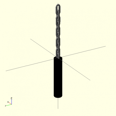
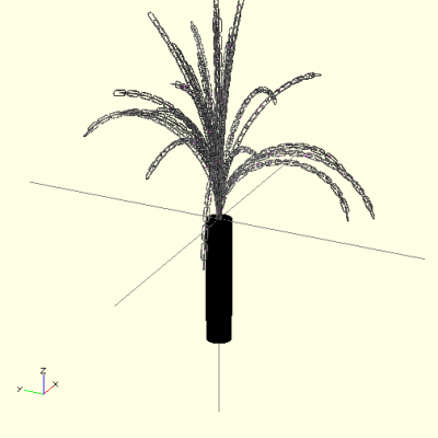
I created customizable renderings of cat o’ nine tails. The number of chains, their lengths and curvature are all customizable. As are the chain link parameters. This is less useful that I first thought it would be, as customizable chain links are pretty pointless. Basically you just change the scale and that can be done with zooming. Otherwise you can warp the dimensions, but that ends up looking not so great either.

The biggest challenge with this project was getting the chain links to properly connect along a curve. Iterating through the rotations along the chain was not as easy as I hoped. I like that my program broke down into nice discrete pieces, though. Outside of setting the parameters, the main function is less than 10 lines long.

Link to Thingiverse

four

A simple, symmetric cat o’ four tails


catOnines_nine catOnines_single

A single chain with thicker links

catOninesRandom

Randomly generated.  Chain number, lengths and curvatures were randomized.


Code is here

1
2
3
4
5
6
7
8
9
10
11
12
13
14
15
16
17
18
19
20
21
22
23
24
25
26
27
28
29
30
31
32
33
34
35
36
37
38
39
40
41
42
43
44
45
46
47
48
49
50
51
52
53
54
55
56
57
58
59
60
61
62
63
64
65
66
67
68
69
70
71
72
73
74
75
76
77
78
79
80
81
82
83
84
85
86
87
88
89
90
91
92
93
94
95
96
97
98
99
100
101
102
103
104
105
106
107
108
109
110
111
112
113
114
115
116
117
118
119
120
121
122
123
124
125
126
127
128
129
130
131
132
133
134
135
136
137
138
139
140
141
142
143
144
145
146
147
148
149
150
151
152
153
154
155
156
157
158
159
pi = 3.145926535;
 
//General Params
 
chains = 9;
 
curvature = 76;
 
//Chain Params
 
links = 50;
 
//Link Parameters
 
smooth = 10; //10
 
thickness = 2; //2
 
height = 16; //16
 
width = 8; //8
 
//Handle
 
color([0,0,0])
 
translate([0,0,-200])
 
cylinder(200,20,20);
 
for ( i=[1 : chains]){
 
rotate(i*360/chains,[0,0,1])
 
chain(links,curvature);
 
}
 
/*
 
for (i = [1 : chains]){
 
rotate(rands(0,360,1)[0],[0,0,1])
 
chain(rands(20,30,1)[0],rands(0,180,1)[0]);
 
}
 
*/
 
module chain(links,curvature){
 
length = (links + 1) * ((height + width)/2 + thickness);
 
radius = length / d2r(curvature);
 
lc = curvature/links;
 
link(smooth,thickness,height,width);
 
if(links > 1){
 
for(i = [1 : links-1]){
 
if( curvature > 0){
 
translate([radius *(1 - cos( i * lc)),0, radius * sin ( i * lc)])
 
rotate(lc*i,[0,1,0])
 
if ( i%2 == 1)
 
{
 
rotate(90*i,[0,0,1])
 
link(smooth,thickness,height,width);
 
} else{
 
link(smooth,thickness,height,width);
 
}
 
}else{
 
translate([0,0,i*(height/2 + width/2 + thickness)])
 
if ( i%2 == 1)
 
{
 
rotate(90*i,[0,0,1])
 
link(smooth,thickness,height,width);
 
} else{
 
link(smooth,thickness,height,width);
 
}
 
}
 
}
 
}
 
}
 
module link(smooth,thickness,height,width){
 
color("Gray"){
 
translate([-width/2, 0, -height/2]){
 
cylinder(height,thickness,thickness);
 
translate([width,0,0]){
 
cylinder(height,thickness,thickness);
 
}
 
for( i = [0 : smooth])
 
{
 
translate([(width/2) - (width/2) * cos(i*180/smooth),
 
0,
 
-(width/2) * sin(i*180/smooth)])
 
sphere(thickness);
 
}
 
for( i = [0 : smooth])
 
{
 
translate([(width/2) - (width/2) * cos(i*180/smooth),
 
0,
 
height + (width/2) * sin(i*180/smooth)])
 
sphere(thickness);
 
}
 
}
 
}
 
}
 
function d2r(theta) = theta*pi/180;

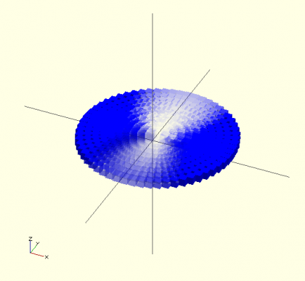
My first idea was to try and generate images of Hyrdrogen wave functions.  The states are controlled by 3 parameters and create interesting distributions.  I played around with trying to represent the wave density below.  However, OpenSCAD does not really play nicely with complicated math (variables in for loops are problems, you can’t really return variables from functions).  Without that, there was really no way to generate the distribution from the parameters.  Even if it had, I’m not sure that I had a good way to do the visualization.  The density plot below was made by discrete spheres with varied alpha values.  Mapping constant probability densities probably would have suited OpenSCAD better, but it still would have required the math.

quantum

Emily Danchik

23 Jan 2014

A parametric pawn by @EmilyDanchik using #OpenSCAD

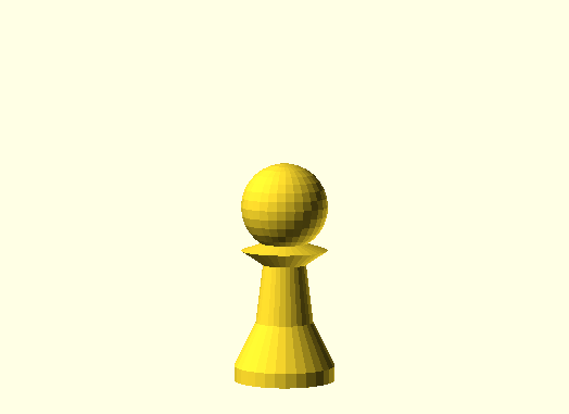
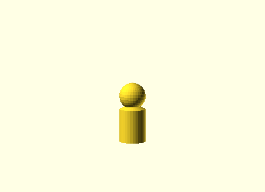
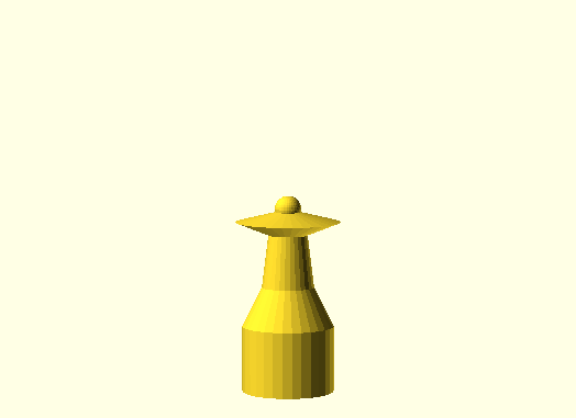
For my object, I created a pawn with several parameters. In my first sketching class, we created our own chess pieces to practice drawing and rendering 3D shapes. OpenSCAD automates part of this process, so I recreated several of my old sketches here:

A pretty pawn

A pretty pawn

Plain pawn

Plain pawn

Pin with a teensy head

Pin with a teensy head

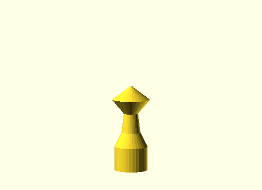
This pawn's collar is higher than it's small head, so it has a cool diamond shape thing going on.

This pawn’s collar is higher than it’s small head, so it has a cool diamond shape thing going on.

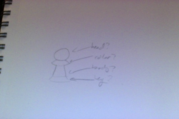
I’m not sure what the proper terminology is for the parts of chess pieces, so I made my own in my sketch:
Photo on 1-23-14 at 2.41 AM


Here is the code for my pawn:

1
2
3
4
5
6
7
8
9
10
11
12
13
14
15
16
17
18
19
20
21
22
23
24
25
26
27
28
29
30
31
32
// Change any of these!
headWidth = 50;
collarHeight = 10;
collar1Width = 80;
collar2Width = 30;
bodyHeight = 40;
bodyWidth = 40;
legHeight = 30;
baseWidth = 70;
baseHeight = 10;
 
// The head
sphere(headWidth/2);
 
// The collar-looking thing
translate([0, 0, -1*headWidth/2]) 
cylinder(h=collarHeight, r1 = collar1Width/2, r2 = 0);
 
translate([0, 0, -1*headWidth/2-collarHeight]) 
cylinder(h=collarHeight, r1 = collar2Width/2, r2 = collar1Width/2);
 
// The body-looking thing
translate([0, 0, -1*headWidth/2-collarHeight-bodyHeight]) 
cylinder(h=bodyHeight, r1= bodyWidth/2, r2= collar2Width/2);
 
// The leg
translate([0, 0, -1*headWidth/2-collarHeight-bodyHeight-legHeight]) 
cylinder(h=legHeight, r1= baseWidth/2, r2= bodyWidth/2);
 
// The base
translate([0, 0, -1*headWidth/2-collarHeight-bodyHeight-legHeight-baseHeight]) 
cylinder(h=baseHeight, r1= baseWidth/2, r2= baseWidth/2);

This code is available at Thingiverse and GitHub. I would consider the design to be useful and interesting, and perhaps beautiful in its simplicity.

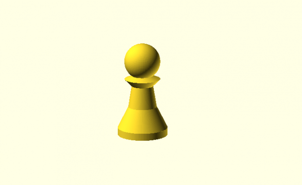
In class, Andrew showed me a way to make the piece look more smooth. Thanks! Check out how good it looks now:

Thanks bro

Thanks bro

The updated code looks like this. I may update the GitHub & Thingiverse to reflect this, giving Andrew credit:

1
2
3
4
5
6
7
8
9
10
11
12
13
14
15
16
17
18
19
20
21
22
23
24
25
26
27
28
29
30
31
32
33
34
// Change any of these!
headWidth = 50;
collarHeight = 10;
collar1Width = 50;
collar2Width = 30;
bodyHeight = 30;
bodyWidth = 40;
legHeight = 30;
baseWidth = 70;
baseHeight = 10;
 
smooth=100;
 
// The head
sphere(headWidth/2, $fn=smooth);
 
// The collar-looking thing
translate([0, 0, -1*headWidth/2]) 
cylinder(h=collarHeight, r1 = collar1Width/2, r2 = 0, $fn=smooth);
 
translate([0, 0, -1*headWidth/2-collarHeight]) 
cylinder(h=collarHeight, r1 = collar2Width/2, r2 = collar1Width/2, $fn=smooth);
 
// The body-looking thing
translate([0, 0, -1*headWidth/2-collarHeight-bodyHeight]) 
cylinder(h=bodyHeight, r1= bodyWidth/2, r2= collar2Width/2, $fn=smooth);
 
// The leg
translate([0, 0, -1*headWidth/2-collarHeight-bodyHeight-legHeight]) 
cylinder(h=legHeight, r1= baseWidth/2, r2= bodyWidth/2, $fn=smooth);
 
// The base
translate([0, 0, -1*headWidth/2-collarHeight-bodyHeight-legHeight-baseHeight]) 
cylinder(h=baseHeight, r1= baseWidth/2, r2= baseWidth/2, $fn=smooth);

Paul Peng

23 Jan 2014

Twitter Summary: @1732051 makes something dumb using #OpenSCAD and cylinders

nicecloseup

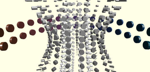
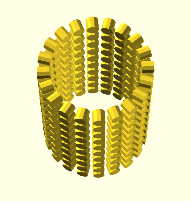
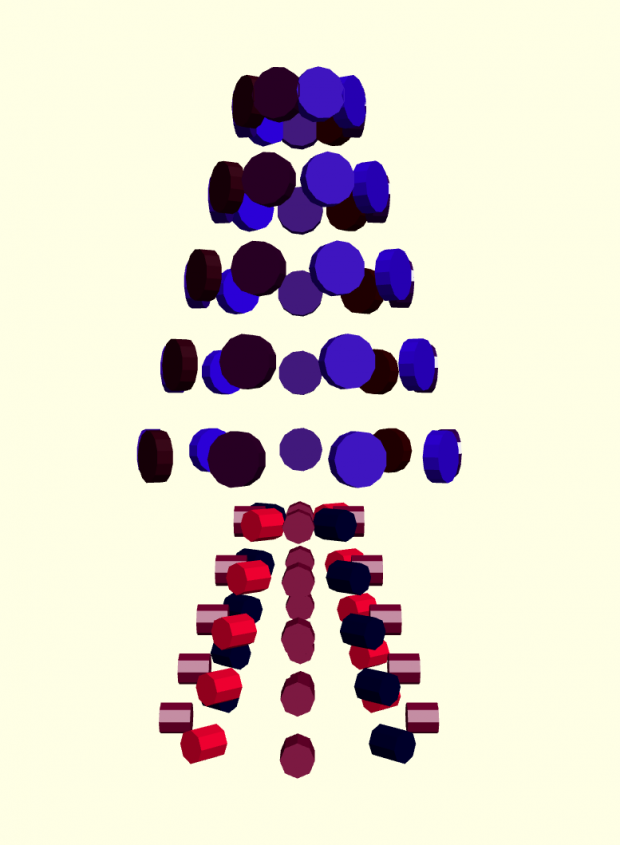
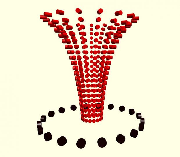
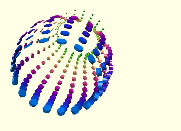
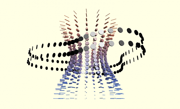
For this project, I began with the idea of creating compartments in a grid formation where a certain repeating element will be altered based on its position in this grid through some mathematical function. Eventually I had this grid wrap around so that it formed a cylindrical shape. In commemoration of this cylindrical grid I made the repeating element a cylinder as well.

template

Above is what this cylinder of cylinders looks like without any modifications. This thing takes a really long to compile!

Screen Shot 2014-01-23 at 12.14.18 AM

The parameters that one would run the function itself include the height of the collection of cylinders, its vertical offset from the center, and the number of rows and columns to include. In addition, a section of the module consisting of various function definitions can be edited by the client to determine the radius of the super-cylinder at a given sub-cylinder and the color, length, and radius of each sub-cylinder based on some mathematical formula involving the row and column of that sub-cylinder. This can be used to produce some pretty nice looking things.

Screen Shot 2014-01-23 at 12.02.33 AM

The main issue I had with OpenSCAD while making this is the fact that it does not seem to support higher-order functions, which would make the implementation of this significantly more elegant since the client would not have to write directly in the module where the guts of the implementation lie. In addition, to render multiple super-cylinders one would have to copy-and-paste the module and give it a different name. Yuck!

bluebulb

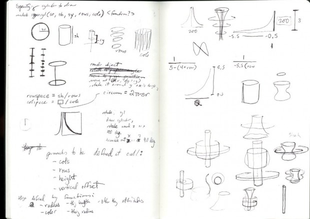
I also chose to work in and take my screencaps from openscad.net since the version of openSCAD I downloaded seemed to render everything in this nice but unchangeable yellow tone, regardless of how many times you call color(). It also seemed to take longer to render the images as well and didn’t produce particularly high-resolution images when I would ask it to export the file as an image. Whatever! I do what I want! Here are some sketches.

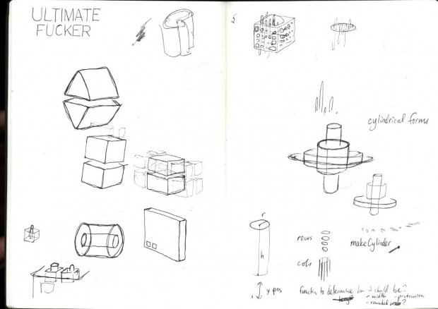
img009 img010

Ignore where it says “ultimate fucker” in all caps on that first page of sketches; that’s for a painting I might make later this year. Here’s one more thing I made with my thing.

bendymid

Interesting? Beautiful? Maybe, but definitely useless. You can’t really 3-D print this either. Nevertheless, it produced some results that I found surprisingly elegant, and is something I would love to use again and take even further if not for OpenSCAD’s inflexibility towards certain things (higher order functions!) and the ridiculously long time it takes to compile for anything relatively large. I will upload this to GitHub and Thingiverse when it’s not 1 in the morning so I can actually show up to this class today Here’s the GitHub link; Thingiverse is coming later.

/* this is my cylinder thing. (my = paul peng)
 * higher order functions are not supported
 * this programming language is shit >_<
 */
 
/*
 * To use, copy supercyl_template and change name to something like
 * "supercyl_a" or something. Change the functions inside s.t. you get
 * cool variations in the way things happen.
 * To draw multiple supercylinders copy the template and give it
 * a different name like "supercyl_b".
 * This would be so much easier with higher order functions :(
 */
 
/* 
 * modified sin and cos for convenience
 * input goes from 0 to 1 instead of 0 to 360
 * output goes from 0 to 1 instead of -1 to 1
 */
function mysin(n) = 0.5 + 0.5*sin(n);
function mycos(n) = 0.5 + 0.5*cos(n);
 
module supercyl_template(h, zoffset, rows, cols) {
    /* user-defined functions, feel free to change */
    /* note: arguments passed are value in range [0, 1) */
    function radfun(row, col) = 25;
    function colorfun(row, col) = [0.5, 0.5, 0.5];
    function nibhfun(row, col) = 6;
    function nibrfun(row, col) = 3;
    /* don't change anything after this */
    rowspace = h / rows;
    colang = 360 / cols;
    for (row = [0 : rows-1]) {
        for (col = [0 : cols-1]) {
            //color(colorfun(row/rows, col/cols))
            rotate([0, 0, colang * col])
            translate([0, radfun(row/rows, col/cols), zoffset - h/2 + rowspace * row + rowspace/2])
            rotate([90, 0, 0])
            cylinder(h = nibhfun(row/rows, col/cols), r = nibrfun(row/rows, col/cols), center = true);
        }
    }
}
 
/* delete this when you put your own stuff in */
supercyl_template(75, 0, 2, 20);

Nastassia Barber

23 Jan 2014

A customizable #openSCAD vase that reflects your body proportions

{ On Thingiverse here.  }

With this project, I chose the qualifications beautiful and interesting and really focused on the idea of making the customization of the object a meaningful experience.  I chose body proportions because they’re intimate facts about a person (which people may or may not be sensitive about) but they are still somewhat recognizable to someone who knows the person well.  Applying these proportions to a vase seemed ideal because it’s a decorative object, and it also may not ‘read’ as a humanoid shape to everyone who sees it out of context.  This allows the person who customizes the vase to see their body in sort of an abstract context, which I thought was interesting.

sketch

mevase3


I actually found working with openSCAD limiting because of my background in regular CAD software.  I didn’t understand how fillets/chamfers/etc were not built-in functions (I really wanted to smooth some of the edges, but the methods I could find were super complicated), and I realized how accustomed I’d become to the normal CAD interface (which I definitely used to make little sculptural things when I was bored at work).  This is definitely just a personal problem, though, and it does take multiple orders of magnitude less time to learn than Pro/Engineer.

The above vase is mine, and here are a couple of my friends next to their vases.

alltogethernow

chest=34; //enter your chest diameter
waist=25; //ender your smallest waist diameter
hips=35; //enter your widest hip diameter
height=64; //enter your height in inches
torso_height=height/2.2;
chest_height=torso_height/3;

union()
{
hull()
{
cylinder(2,7,7);
translate([0,0,2])cylinder(5,5,5);
}
translate([0,0,7])cylinder(10,5,chest/2);
translate([0,0,17]) cylinder(chest_height,chest/2,chest/2-3);
translate([0,0,chest_height+17]) cylinder(chest_height,chest/2-3, waist/2);
translate([0,0,chest_height*2+17]) cylinder(chest_height, waist/2, hips/2);
translate([0,0,chest_height*3+17]) cylinder(torso_height*1.4, hips/2, 8);
translate([0,0,torso_height*2.4+17]) cylinder(2,10,10);
}

Sama Kanbour

23 Jan 2014

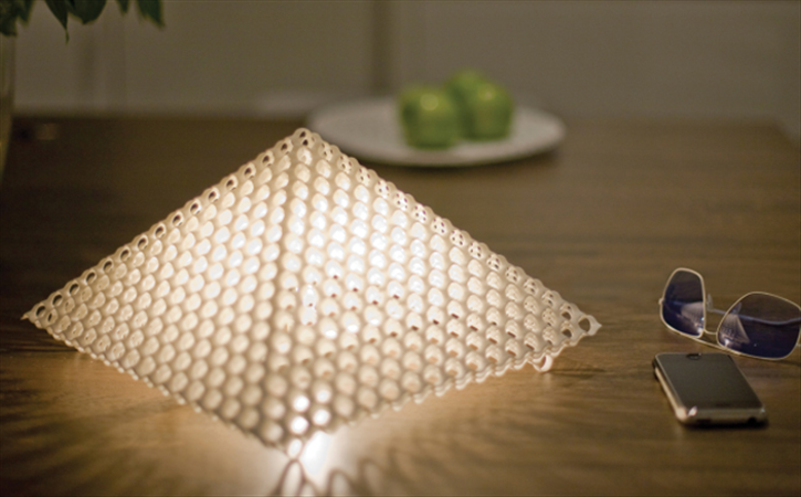
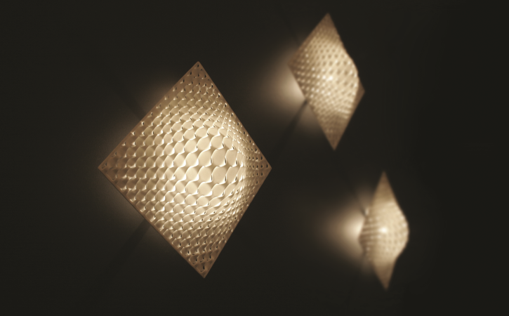
Lighting geometric design created with #OpenSCAD by @samakanbour.

I really love these beautifully designed candle containers that diffuse light through their holes. Useful, useable and desirable, these objects are mass-produced around the world. I can easily imagine consumers personalizing and purchasing them to decorate their homes and offices. Inspired by the Freshfiber lighting collection, I tried to capture a triangular geometric design, and generate different versions by playing with its parameters. I am pleased with the simplicity and depth of the designs, but I am not entirely satisfied with their limited variations. I would have loved having other than triangular shapes, such as circular or cubic.

FAL

FOC

Thing Link

GitHub

light

1
2
3
4
5
6
7
8
9
10
11
12
13
14
15
16
17
18
19
20
21
22
23
24
25
26
27
28
29
30
31
32
33
34
35
36
37
38
39
// inspired by NateTG 
 
maxlevel = 3;
size = 30;
thickness = 10;
 
difference()  {
	color("MediumOrchid") sierpinski(side=size,maxlevel=maxlevel);
	middle(size - thickness);
	cylinder(r = 3/maxlevel, h = 50, center=true);
	rotate([90]) cylinder(r = 3/maxlevel, h = 50, center=true);
	rotate([0, 90]) cylinder(r = 3/maxlevel, h = 50, center=true);
}
 
module triangle(side, maxlevel=3) {
	difference() {
	polyhedron(points=[[side,0,0],[0,side,0],[0,0,side],[-side,0,0],[0,-side,0],[0,0,-side]], 
	triangles=[[0,2,1],[0,4,2],[0,5,4],[0,1,5],[3,1,2],[3,2,4],[3,4,5],[3,5,1]]);	
	rotate([45]) cylinder(r = 2/maxlevel, h = 50, center=true);
	rotate([-45]) cylinder(r = 2/maxlevel, h = 50, center=true);
	rotate([0, -45]) cylinder(r = 2/maxlevel, h = 50, center=true);
	rotate([0, 45]) cylinder(r = 2/maxlevel, h = 50, center=true);
	}
}
 
module middle(side) {
polyhedron(points=[[side,0,0],[0,side,0],[0,0,side],[-side,0,0],[0,-side,0],[0,0,-side]], triangles=[[0,2,1],[0,4,2],[0,5,4],[0,1,5],[3,1,2],[3,2,4],[3,4,5],[3,5,1]]);	
 
}
 
module sierpinski(side=1,maxlevel=3,level=1) {
	for(i =[[side*sqrt(2)/4,0,0],[0,side*sqrt(2)/4,0],[0,0,side*sqrt(2)/4],[-side*sqrt(2)/4,0,0],[0,-side*sqrt(2)/4,0],	[0,0,-side*sqrt(2)/4]]) {
		if(level<maxlevel) {
			translate(i) sierpinski(side=side/2,maxlevel=maxlevel,level=level+1);
		} else {
			translate(i) triangle(side=side*sqrt(2)/4, maxlevel=maxlevel);
		}
	}
}


Spencer Barton

23 Jan 2014

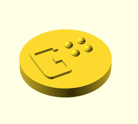
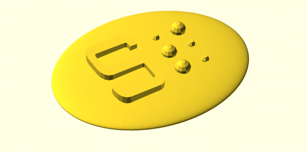
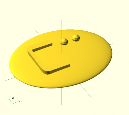
A customizable #OpenSCAD braille fridge magnet

magnetG

magnetS

magnetZ

2014-01-23 00.15.27

A customizable #OpenSCAD braille fridge magnet

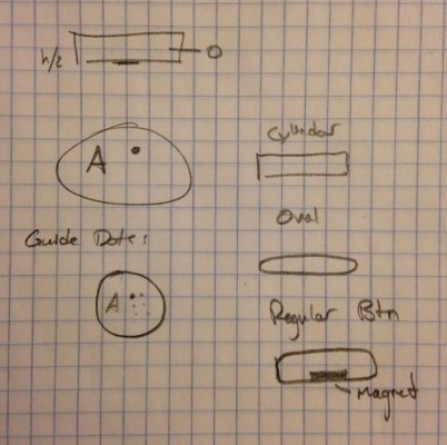
The advantage of parametric CAD design is flexibility. I decided I should work with forms where there was a need for translation between data and a physical shape. Braille presented itself as a unique opportunity to create something useful. I ran into some major limitations with openSCAD, in particular its strange use of variables . Currently my sketches can only convert letters but not numbers because I had difficulty updating variables during execution. I liked utilizing braille since there is a real potential need. I however have limited experience with the blind so I took a stab in the dark when creating an object that I though had some value. Bilingual fridge magnets (since both the braille and the regular letter are there) may be nice for some people but certainly are not a necessary item.

Github
Thingiverse

1
2
3
4
5
6
7
8
9
10
11
12
13
14
15
16
17
18
19
20
21
22
23
24
25
26
27
28
29
30
31
32
33
34
35
36
37
38
39
40
41
42
43
44
45
46
47
48
49
50
51
52
53
54
55
56
57
58
59
60
61
62
63
64
65
66
67
68
69
70
71
72
73
74
75
76
77
78
79
80
81
82
83
84
85
86
87
88
89
90
91
92
93
94
95
96
97
98
99
100
101
102
103
104
105
106
107
108
109
110
111
112
113
114
115
116
117
118
119
120
121
122
123
124
/*
    Braille Fridge Magnet
    Spencer Barton
 
    based on http://www.thingiverse.com/thing:47411 by kitwallace
 
    Directions: Upload your alphebetic character [A-Z,a-z] to be converted to braille and placed on a tag
 
*/
 
use <write .scad>
 
/*===================================================
  Global Vars
  =================================================== */
 
// encodings
font_charKeys = ["a", "A", "b", "B", "c", "C", "d", "D", "e", "E", "f", "F", "g", "G", "h", "H", "i", "I", "j", "J", "k", "K", "l", "L", "m", "M", "n", "N", "o", "O", "p", "P", "q", "Q", "r", "R", "s", "S", "t", "T", "u", "U", "v", "V", "w", "W", "x", "X", "y", "Y", "z", "Z", ",", ";", ":", ".", "!", "(", ")", "?", "\"", "*", "'", "-"];
font_charValues = [[1], [1], [1, 2], [1, 2], [1, 4], [1, 4], [1, 4, 5], [1, 4, 5], [1, 5], [1, 5], [1, 2, 4], [1, 2, 4], [1, 2, 4, 5], [1, 2, 4, 5], [1, 2, 5], [1, 2, 5], [2, 4], [2, 4], [2, 4, 5], [2, 4, 5], [1, 3], [1, 3], [1, 2, 3], [1, 2, 3], [1, 3, 4], [1, 3, 4], [1, 3, 4, 5], [1, 3, 4, 5], [1, 3, 5], [1, 3, 5], [1, 2, 3, 4], [1, 2, 3, 4], [1, 2, 3, 4, 5], [1, 2, 3, 4, 5], [1, 2, 3, 5], [1, 2, 3, 5], [2, 3, 4], [2, 3, 4], [2, 3, 4, 5], [2, 3, 4, 5], [1, 3, 6], [1, 3, 6], [1, 2, 3, 6], [1, 2, 3, 6], [2, 4, 5, 6], [2, 4, 5, 6], [1, 3, 4, 6], [1, 3, 4, 6], [1, 3, 4, 5, 6], [1, 3, 4, 5, 6], [1, 3, 5, 6], [1, 3, 5, 6], [2], [2, 3], [2, 5], [2, 5, 6], [2, 3, 5], [2, 3, 5, 6], [2, 3, 5, 6], [2, 3, 6], [2, 3, 6], [3, 5], [3], [3, 6]];
 
// compile vars
$fa = 0.01; $fs = 0.5; 
 
// global dimensions from http://www.brailleauthority.org/sizespacingofbraille/sizespacingofbraille.pdf
 
// these dimensions for braille letters
font_dotHeight = 0.7;
font_dotBase = 1.6;  
font_dotRadius = font_dotBase /2;
font_dotWidth= 2.54;
font_charWidth = 7.62;
font_lineHeight = 11; 
 
// compute the sphere to make the raised dot
font_dotSphereRadius =  chord_radius(font_dotBase,font_dotHeight);
font_dotSphereOffset = -(cylinderDepth - 2.0)/2.0 + font_dotSphereRadius - font_dotHeight;
 
// inputs
letter = "C"; 
cylinderRadius = 8.0;
cylinderDepth = 2.0;
magnetRadius = 2.0;
magnetDepth = 1.0;
guideDots = true;
cylinderMagnet = false;
 
/*===================================================
  Functions
  =================================================== */
 
// dot is not a hemisphere 
function chord_radius(length,height) = ( length * length /(4 * height) + height)/2;
 
/*===================================================
  Modules
  =================================================== */
 
module drawDot(location, radius) {  
    translate(location) 
       translate ([0,0, -font_dotSphereOffset ]) 
			sphere(radius);
}
 
module drawCharacter(charMap) {
     for(i = [0: len(charMap)-1]) 
        assign(dot = charMap[i] - 1)
        drawDot(   [floor(dot / 3) * font_dotWidth,  -((dot %3) * font_dotWidth),   0],  font_dotRadius );
}
 
 
module transcribeChar(char) {
    // match with one from alphabet
    for(j = [0:len(font_charKeys)-1]) {
        if(font_charKeys[j] == char) {
            drawCharacter(font_charValues[j]);
				echo(font_charKeys[j]);
        }
    }
}
 
module drawGuideDots() {
	  assign( charMap = [1,2,3,4,5,6] )
     for(i = [0: len(charMap)-1]) 
        assign(dot = charMap[i] - 1)
        drawDot(   [floor(dot / 3) * font_dotWidth,  -((dot %3) * font_dotWidth),   0],  font_dotRadius * .5 );
}
 
module magnet(letter) {
 
     difference () {
        union() {
            // main rectangle
            if (cylinderMagnet == true) {
					cylinder(r = cylinderRadius,h = cylinderDepth);
				} else {
					translate([0,0,cylinderDepth/2])
						resize(newsize=[cylinderRadius*2.5,cylinderRadius*2,cylinderDepth]) sphere(r=cylinderRadius);  
				}
            // write regular letter
            translate([-cylinderRadius/3.0,0,cylinderDepth])
					write(letter,t=font_dotSphereOffset,h=cylinderRadius,center=true, font = "orbitron.dxf");
				// chars
				translate([cylinderRadius/4.0,font_dotWidth,cylinderDepth])
            	transcribeChar(letter);
				// indicators
				if (guideDots == true) {
					translate([cylinderRadius/4.0,font_dotWidth,cylinderDepth])
						drawGuideDots();
				}
        } // end union
 
        // hole for magnet
		  translate([0,0,-.5])
            cylinder(r=magnetRadius,h=magnetDepth+1);  
    }
 
}
 
/*===================================================
  Run Main Module
  =================================================== */
 
magnet(letter);
</write>

13: Joels OpenScad

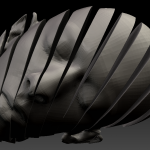
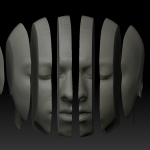
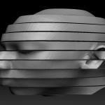
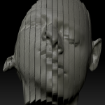
Tweetable Summary: Slice is a parametric #openScad tool for slicing and deforming models. @JoelSSimon.

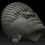
I was incredibly excited to use openScad to parametrically deform figurative models.  The brain is particularly good at identifying other human faces and very interesting properties arise when deformations occur. Geometric deformations are nice in that they are a type of deformations orthogonal to those that lead into uncanny valley.  I wanted a very simple action that could have a wide range of utility and leave the elegance of the human form intact. Slices are very simple in nature but have many parameters which is why I thought they could be interesting to experiment with. With regarding criticism, I see this as the beginning of a much larger body of work so it feels premature to do so. So my criticism is that I didn’t try more things.

Also I want to touch on the fact that this is the second project using my own head. I don’t enjoy looking at my face any more than you do. I also find it pretentious and weird, but it is the only high quality head model that I own. It also gives me freedom to do ugly and bizarre things to it.

Parameters : [stl file, thickness of each slice as % width, transformation and rotation function to apply to each slice]

Thingverse

Github

/*
        Joel Simon. Jan 23, 2103. joelsimon.net.
*/
 
headWidth = 250; // y
headDepth = 250; // x
headHeight= 401; // z
 
//If unkown, Use this cube to measure the objects dimensions.
//centerCube(headDepth,headWidth, headHeight);
 
module centerCube(x,y, z) {
        color("Yellow",0.3) translate([-x/2,-y/2,-z/2]) cube([x,y,z]);
}
 
module faceSlice(a, b, tx,ty,tz, rx, ry, rz) {
        startY = (a * headWidth) - headWidth/2;
        endY = (b * headWidth) - headWidth/2;
 
        translate([tx,ty,tz])  rotate([-90+rx,ry,rz])  intersection() { 
                color("Yellow", .5) translate([-headDepth/2,startY,-headHeight/2]) cube([headDepth, endY-startY, headHeight]);
                rotate([90,0,0]) translate([50,-2,-200]) rotate([90,0,0]) import("/Users/joelsimon/Documents/3dModeling/JoelHead/midRes.stl");                
        }
}
 
module main(step, skip, tx, ty, tz, rx, ry, rz) {
        for (i = [0 : (1/step)] ){
                if (i%skip == 0) { 
                        faceSlice((i*step)-step, (i*step), 
                                                tx, ty, tz,
                                                (-rx/2) + (i*step)*(rx/2),
                                                (-ry/2) + (i*step)*(ry/2),
                                                (-rz/2) + (i*step)*(rz/2));
                }
        }
}
 
main(.05, 1, 0,0,0,0,0,180);

Parametric Robot Head

A 3D robot head that your can control with your m̶i̶n̶d̶ programs.

Diagonal1
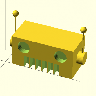
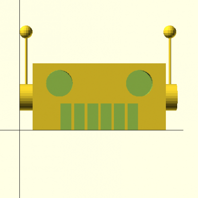
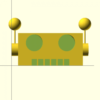
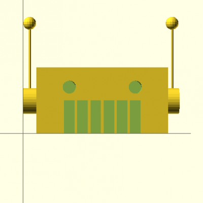
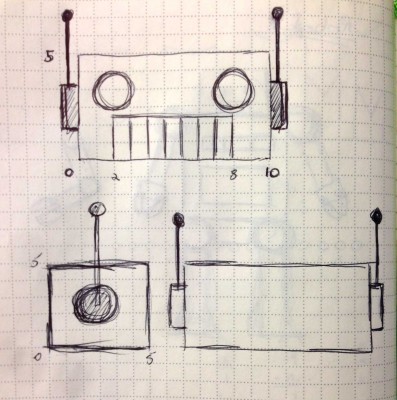
Robots are cool, right? So a parametric model of a robot head where a user can adjust the size of various facial features must be super fly. At the very least it is Beautiful, Interesting, Useful.  I’m not really sure how this topic popped into my head, but I am pretty pleased for the first thing I ever computationally modeled in 3D.

The code allows for the adjustment of 5 attributes: antenna height, antenna ball radius, eye diameter, the spacing between the eyes, and the hight of the mouth. I think that if animated these attributes, when manipulated programmatically, could resemble dialog, facial expressions, or even emotional states.

Code on GitHub: https://github.com/jeffcrossman/Parametric_Robot

Available on Thingiverse

Front1

Front2

Front3


robotsketch


1
2
3
4
5
6
7
8
9
10
11
12
13
14
15
16
17
18
19
20
21
22
23
24
25
26
27
28
29
30
31
32
33
34
35
36
37
38
39
40
41
42
43
44
45
46
47
48
49
50
51
52
53
54
55
56
57
58
59
60
61
62
63
64
65
66
67
68
69
70
71
72
73
74
75
76
77
78
79
80
81
82
83
84
85
86
87
88
89
90
////////////////////////////////////////
//
//     By: Jeff Crossman
//	  For: Golan Levin's IACD 2014
//		   Carnegie Mellon University
//	Title: Parametric Robot Head
//
/////////////////////////////////////// 
 
////////////////////////////////////////
//									//
//		PARAMETRIC PARAMETERS		//
//									//
////////////////////////////////////////
 
AntennaHeight = 50;		// Default: 50
AntennaBallRadius = 5;	// Default: 5
EyeDiameter = 10;		// Default: 10
EyeSpacingOffset = 0;	// Default: 0
MouthHeight = 20;		// Default: 20
 
//////////////   END   /////////////////
 
// Head
translate([10, 0, 0]){
difference() {
	// Base head
	cube([100, 50, 50]);
 
	// Mouth
	translate([21, 0, 0]){
		cube([8, 10, MouthHeight]);
	}
	translate([31, 0, 0]){
		cube([8, 10, MouthHeight]);
	}
	translate([41, 0, 0]){
		cube([8, 10, MouthHeight]);
	}
	translate([51, 0, 0]){
		cube([8, 10, MouthHeight]);
	}
	translate([61, 0, 0]){
		cube([8, 10, MouthHeight]);
	}
	translate([71, 0, 0]){
		cube([8, 10, MouthHeight]);
	}
 
	// Left Eye
	translate([20+EyeSpacingOffset, 4, 35]){
		rotate(a=[90, 0, 0]) {
			cylinder(10, EyeDiameter, EyeDiameter, center=true);
		}
	}
 
	// Right Eye
	translate([80-EyeSpacingOffset, 4, 35]){
		rotate(a=[90, 0, 0]) {
			cylinder(10, EyeDiameter, EyeDiameter, center=true);
		}
	}
}
}
 
// Left Ear
translate([5, 25, 25]){
	rotate(a=[0, 90, 0]) {
		cylinder(10, 10, 10, center=true);
	}
}
translate([5, 25, (25+(AntennaHeight/2))]){
	cylinder(AntennaHeight, 1, 1, center=true);
}
translate([5, 25, 25+AntennaHeight]){
	sphere(AntennaBallRadius);
}
 
// Right Ear
translate([115, 25, 25]){
	rotate(a=[0, 90, 0]) {
		cylinder(10, 10, 10, center=true);
	}
}
translate([115, 25, (25+(AntennaHeight/2))]){
	cylinder(AntennaHeight, 1, 1, center=true);
}
translate([115, 25, 25+AntennaHeight]){
	sphere(AntennaBallRadius);
}

Andrew Russell

22 Jan 2014

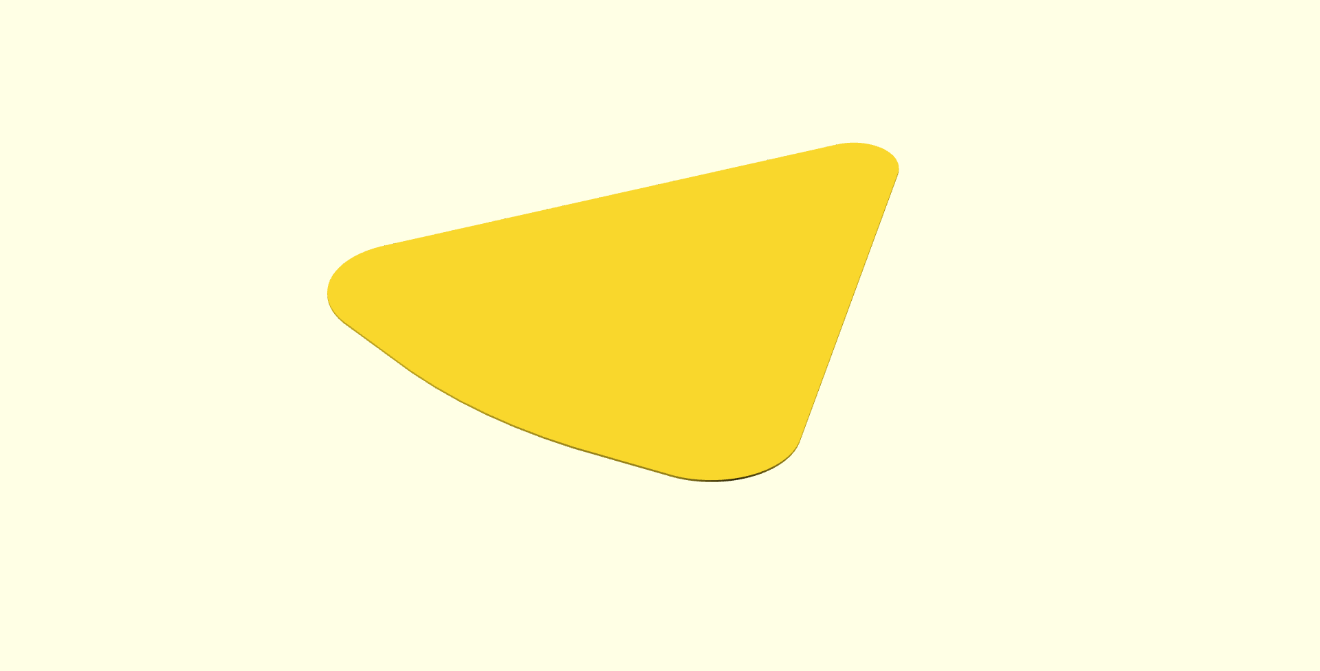
Parametric Guitar Pick by Andrew Russell is a 3d printable guitar pick where the size and shape can be easily modified.

Guitars

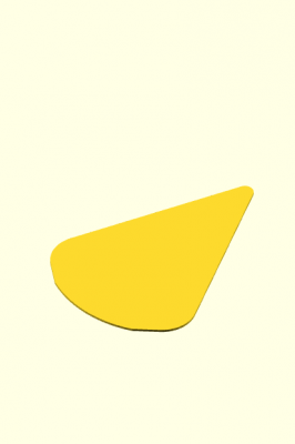
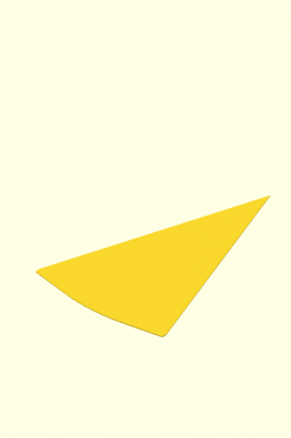
Being a musician, I wanted to create a parametric object that I could use and customize for myself. Guitar picks usually come in specific sizes and thicknesses. I feel like there is an opportunity for personalized guitar picks to be useful. Don’t like the rounded corners? Remove them. 1mm is too thick, yet 0.88mm is too thin? Choose a value in between.

The user can customize the following attributes:

  • height
  • weight
  • thickness
  • rounded corner radius
  • rounded bottom radius

I was planning on allowing all edges to be rounded, but there were more complications than I first expected. I also set stretch goals to allow concave and sharkfin edges but I did not meet those goals.


Default Guitar Pick

“Standard” guitar pick

Flat Bottom

Really Thick

Sharp Edges

Github

ThingIVerse

1
2
3
4
5
6
7
8
9
10
11
12
13
14
15
16
17
18
19
20
21
22
23
24
25
26
27
28
29
30
31
32
33
34
35
36
37
38
39
40
41
42
43
44
45
46
47
48
49
50
51
52
53
54
55
56
57
58
59
60
61
62
63
64
65
// preview[view:south, tilt:top]
 
/* [Main] */
 
//how wide to make the guitar pick
base = 250;
 
//how tall to make the guitar pick
height = 300;
 
//how thick to make the guitar pick
thickness = 1;
 
//how rounded to make the corners
radii = [40, 40, 20];
 
//how curved to make the base (0 is straight)
curve = 250;
 
//adjusts how close the curve is to the center of the pick
curve_offset = 14;
 
//how smooth to render all circles
smooth = 100;
 
module pick(base, height, t, r, curve, co) {
  r0 = max(radii[0], 0.01);
  r1 = max(radii[1], 0.01);
  r2 = max(radii[2], 0.01);
 
  lw = r0 + r1;
  lh = r2 + max(r0, r1);
 
  hull()
  {
    translate([r0, r0, 0]) {
      cylinder(r=r0, h=t, $fn=smooth);
    }
 
    translate([base-r1, r1, 0]) {
      cylinder(r=r1, h=t, $fn=smooth);
    }
 
    translate([(base-r1+r0)/2, height-lh, 0]) {
      cylinder(r=r2, h=t, $fn=smooth);
    }
 
    if (curve > 0) {
translate([base/2, curve-co, 0])
difference() {
  rotate_extrude($fn=smooth)
    translate([curve-.01, 0, 0])
      square([.01, t]);
  translate([base/2-lw/2, -curve, -1])
    cube([curve, curve*2, t+1]);
  translate([-curve, 0, -1])
    cube([curve*2, curve, t+1]);
  translate([-curve-(base/2-lw/2), -curve, -1])
    cube([curve, curve, t+1]);
}
    }
  }
}
 
pick(base, height, thickness, radii, curve, curve_offset);