Billy Keyes – Final Project – SketchSynth
[vimeo https://vimeo.com/42053193 w=600&h=338]
SketchSynth: A Drawable OSC Control Surface
SketchSynth lets anyone create their own control panels with just a marker and a piece of paper. Once drawn, the controller sends Open Sound Control (OSC) messages to anything that can receive them; in this case, a simple synthesizer running in Pure Data. It’s a fun toy that also demonstrates the possibilities of adding digital interaction to sketched or otherwise non-digital interfaces.
Background
Ever since I was little, I’ve been fascinated by control panels. In elementary school, my neighbor and I would spend our bus rides pretending to operate incredible imaginary machines with cardboard controllers we drew, cut, and taped the night before. Even now, I pause when I see desks covered in gauges, switches, knobs, and buttons, wondering what they all do. At Golan’s suggestion, I tried to capture some of that excitement, updated for an age where imagining that your picture of a switch does something just isn’t as satisfying.
The advantage my eight-year-old self still has is variety. By necessity, the visual language SketchSynth can handle is limited to three input types, illustrated below. Despite this, I think it covers most control possibilities: many knobs are just sliders that take up less space and many buttons are just switches in a different form. Outputs, like gauges and indicator lights, are also missing, but with a general purpose surface it’s unclear what they would display.

While the program is designed to recognize these symbols, it doesn’t reject all other marks. If you like, you can draw anything and see what it is interpreted as.
Technical Details
SketchSynth is built on openFrameworks and makes heavy use of Kyle McDonald’s excellent ofxCv addon, which integrates the powerful OpenCV library into openFrameworks. A standard webcam looks down at the paper and detects both controls and hands. To prevent confusion, there are two modes: EDIT and PLAY. The system basically does nothing in EDIT mode, allowing you do draw controls. When you switch to PLAY mode, the controls are detected. From then on, you can interact with any detected controls. While an infrared camera is ideal to prevent interference from the projection, I had to make due with a standard color camera when my IR conversion didn’t go as planned. Projector interference is acceptably eliminated by looking for the hand in the green channel of the video and projecting controls only in the red and blue channels.
Controls are detected by finding contours (blobs) in an edge-detected version of the image. Ratios of the areas of enclosing shapes to the actual areas of the blobs are used to determine the type of each control. Hands are detected by subtracting the constant background and looking for blobs. The contour of the largest blob is smooth and the finger is assumed to be the point farthest away from the center of the blob. The system can’t actually tell when a person touches the paper, but this seems to work out alright in practice. Dilation and erosion are used heavily to improve the blobs and reject noise.
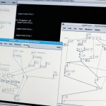
The camera and projector are aligned by clicking on the four corners of a projected rectangle (as seen by the camera) when the program starts up. This behind-the-scenes video shows how the process works and what the setup/debug screen looks like.
[vimeo https://vimeo.com/42053693 w=600&h=338]
You can get the source code on Github (for Linux).
Images
-
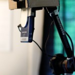
- Camera and pico projector

-
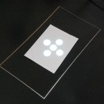
- Calibration rectangle
-
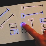
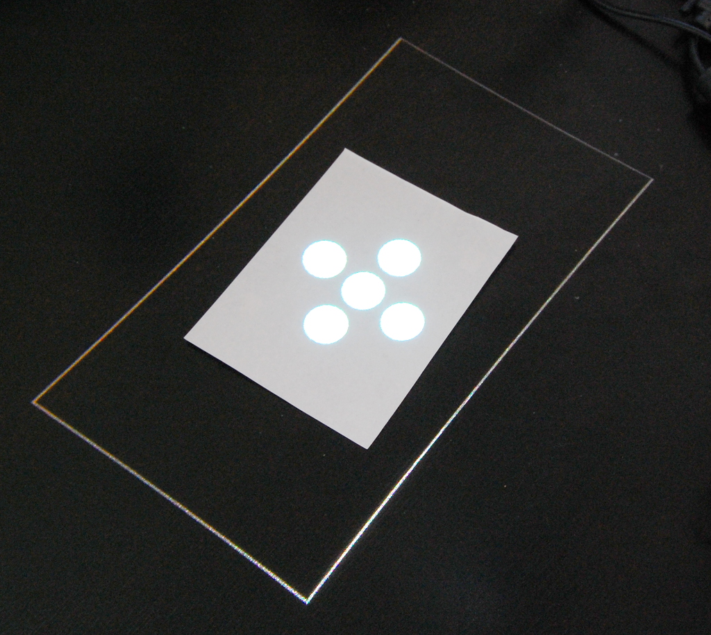
- Projection

-
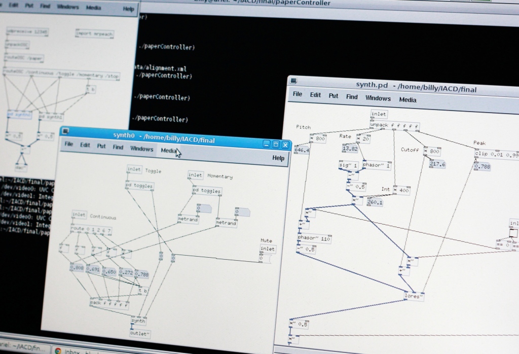
- Pd synthesizer patch
-
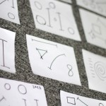
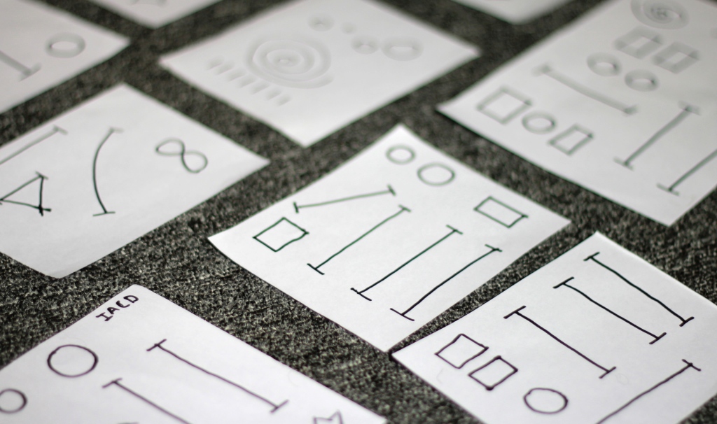
- Some panels people drew at the final show
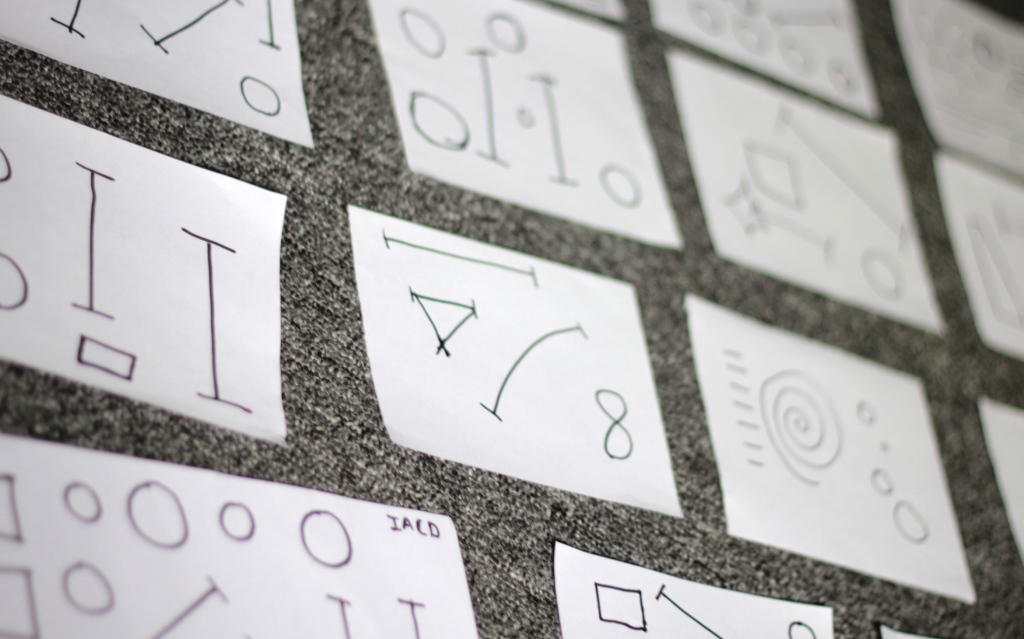
-
- More panels people drew at the final show